volkswagen Workshop Repair Guides

Volkswagen Workshop Service and Repair Manuals

Repairing subframe > < Assembly overview: subframe made from aluminium, final drive (four-wheel drive)
Removing and installing rear axle
Special tools and workshop equipment required
   
t  Torque wrench -V.A.G 1332-
  W00-0428
t  Engine and gearbox jack -V.A.G 1383 A-
Removing subframe with attachments
  Note
Please note that subsequent assembly work for which the hexagon or twelve-point bolt of the drive shaft has to be loosened requires that the vehicle is stood on its wheels. Loosen hexagon bolt of drive shaft → Chapter or loosen twelve-point bolt of drive shaft → Chapter or → Chapter.
–  Remove wheels.
–  Remove coil springs → Chapter.
–  Remove front and rear exhaust system silencer → Rep. gr.26.
–  Disconnect electrical connections between rear axle and body.
  W00-0120
–  Remove bolt -arrow-.
  A42-0421
–  Lever off retainer -1- for handbrake cable.
–  Press lever -2- in direction of arrow and unhook handbrake cable -3-.
  A46-0305
–  Unscrew hexagon bolt -1- and detach handbrake cable -2- from brake cable bracket.
  A46-0306
Vehicles with retainer for hand brake cable
–  Remove retainer -1- by pushing out inner pin of rivet -arrow-.
Continuation for all vehicles
  N42-10240
–  Unclip speed sensor wire from retainer -1--arrows-.
  N42-10342
–  Disconnect brake lines, items -1- and -2-.
  A42-10020
–  Mark installation position of mounting bracket on body.
–  Remove bolts -arrows-.
  A42-0431
–  Check whether marks (spots of paint) are present on flexible coupling and final drive flange -arrows-. If no marks are present, mark positions of flexible coupling and final drive flange relative to each other -arrows-.
  N39-0836
–  Unbolt rear propshaft tube with flexible coupling and vibration damper from rear final drive -arrows-.
  A39-0281
–  Unscrew centre bearing bolts -arrows- two turns.
  A39-0280
–  Support propshaft on tunnel support using a wooden block.
–  Push rear propshaft tube towards gearbox as far as possible.
  A37-10002
–  Now secure vehicle to lifting platform on both sides using tensioning straps-T10038-.
  WARNING
If the vehicle is not strapped down, there is a great danger that the vehicle will slip off the lifting platform!
  N42-10114
–  Position engine and gearbox jack -V.A.G 1383 A- under subframe using universal gearbox mounting -V.A.G 1359/2- and secure with tensioning strap.
  A42-10022
–  Unscrew one hexagon bolt -1- or -2- on both sides.
  Note
Only the left side of vehicle is shown to improve clarity.
  A42-10021
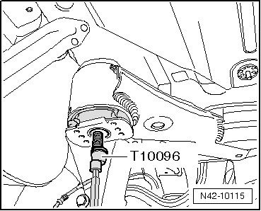
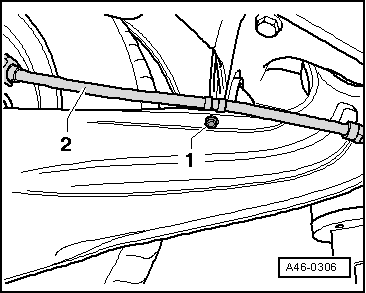
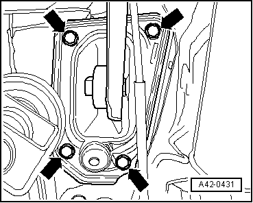
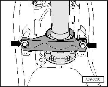
–  Fix position of subframe using 2 locating pins -T10096- and tighten to 20 Nm.
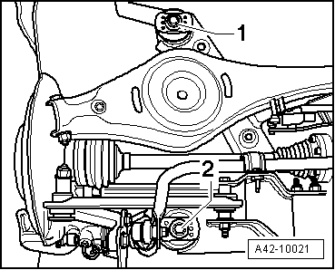
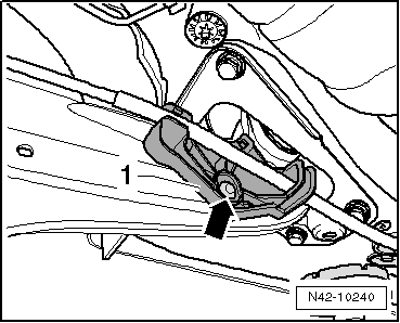
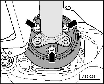
–  Unscrew remaining 2 bolts from subframe.
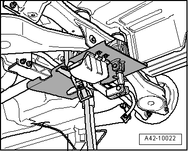
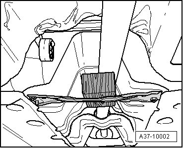
–  Carefully lower subframe with attachments.
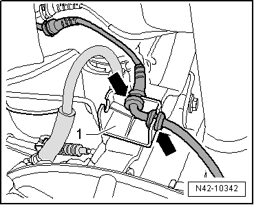
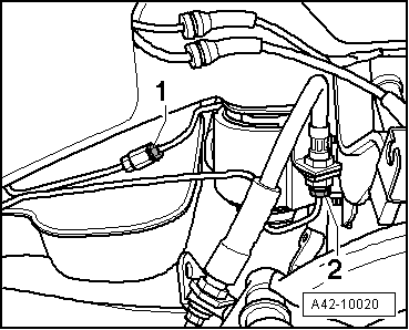
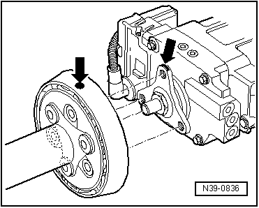
  Note
When lowering, ensure sufficient clearance of brake lines, electrical cables and centring pin to propshaft.
Installing subframe with attachments
Install in reverse order. In the process, note the following:
Attach propshaft to rear final drive → Final drive 02D; Rep. gr.39.
–  Bleed brake system → Rep. gr.47 → Rep. gr.47.
–  Perform wheel alignment → Chapter.
  Note
If an aluminium subframe is to be replaced by one made of steel, then please proceed with the following work sequence → Anchor.
  N42-10115
Specified torques
ComponentSpecified torque
Subframe to body
t  Use new bolts
90 Nm + 90°
Shock absorber to wheel bearing housing180 Nm
Mounting bracket to body
t  Use new bolts
50 Nm + 45°
Handbrake cable to trailing arm
→ Brake systems; Rep. gr.46


Repairing subframe > < Assembly overview: subframe made from aluminium, final drive (four-wheel drive)