volkswagen Workshop Repair Guides

Volkswagen Workshop Service and Repair Manuals

Control units > < Electronics boxes
Removing and installing E-box on left side of engine compartment
  Note
One of two different E-boxes are fitted depending on the level of equipment (high or low). The following illustration show the „High“ version. Removing and installing the „Low“ version is performed in the same manner.
  Caution
When batteries are disconnected and reconnected, the procedure described in the workshop manual must be strictly observed → Chapter.
Removing:
–  Disconnect battery → Chapter.
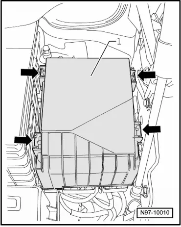
Vehicles ► 05.04:
   
–  Release clips -arrows- and pull cover of E-box -1- off upwards.
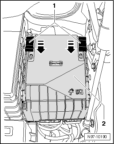
Vehicles 05.04 ►:
  N97-10010
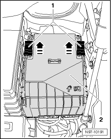
–  Push safety clip -1- in direction of -arrow- and remove cover from E-box -2- upwards.
All vehicles:
  Note
Mark position of wiring connections in respect of connections on E-box.
  N97-10190
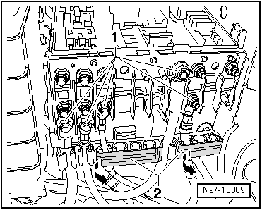
–  Remove hexagon nuts -1-.
–  Open -arrows- covers -2- of cable guides on E-box.
–  Remove wiring from stud connections.
–  Unclip wiring from cable guides.
  Note
The following illustration shows the „High“ version of the E-box. Removing and installing the „Low“ version is performed in the same manner.
  N97-10009
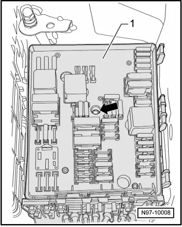
–  Remove central securing bolt -arrow- from E-box -1-.
  Note
When the central securing screw -arrow- is unscrewed, the E-box -1- is pushed upwards off the E-box mounting.
–  Pull E-box -1- upwards off bracket of E-box.
  Note
  N97-10008
For removal of the flat contact housing -1-, the air filter housing (on vehicles with diesel engine only), the battery and the battery carrier must be removed.
–  If necessary, remove air filter housing.
–  Remove battery → Chapter.
  N97-10007
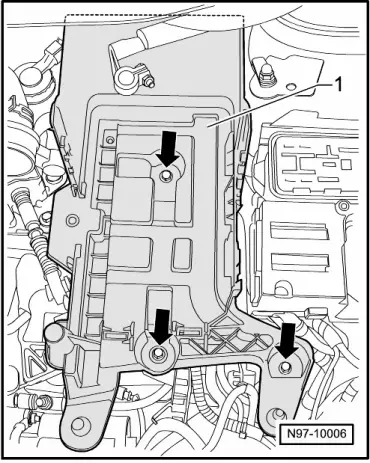
–  Remove securing bolts -arrows- for battery carrier -1-.
–  Take battery carrier -1- out of vehicle.
  N97-10006
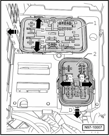
–  Press tabs apart on retainer of E-box -arrows B- and slide flat contact housing -1- sideways -arrow A- out of retainer of E-box.
Vehicles with „High“ version E-box:
–  Press tabs apart on bracket of E-box -arrows C- and slide flat contact housing -2- forwards -arrow D- out of bracket of E-box.
All vehicles:
  N97-10007
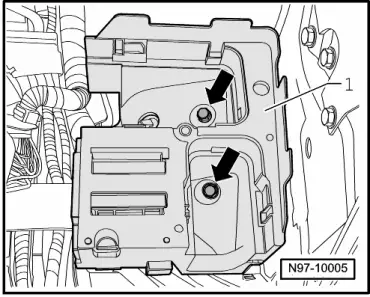
–  Remove securing nuts -arrows- from bracket of E-box -1-.
  Note
The installation of an additional relay carrier depends entirely on the vehicle equipment.
  N97-10005
–  Pull bracket of E-box -1- upwards off studs (be careful not to stretch wiring of additional relay carrier).
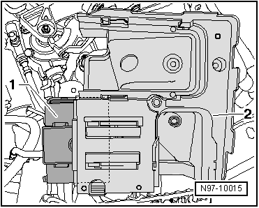
–  Unclip additional relay carrier -1- sideways out of retainer of E-box -2-.
–  Take bracket of E-box -2- out of vehicle.
Installing:
Installation is carried out in the reverse order. When installing observe the following:
  N97-10015
–  Reconnect wiring -1- to E-box, to positions marked before removal → Current flow diagrams, Electrical fault finding and Fitting locations.
–  Tighten threaded connections to specified torques → Chapter.
Vehicles ► 05.04:
  Note
  N97-10009
Ensure when installing the E-box that the cover is clipped in correctly -arrow-.
Vehicles 05.04 ►:
  N97-10010
–  Mount cover -2- on E-box and push safety clip -1- in direction of -arrow- until cover -2- engages.
  Note
Then check whether the cover -2- of the E-box is engaged correctly.
  N97-10191

Control units > < Electronics boxes