
Golf Mk6
|
|

| Special tools and workshop equipment required |
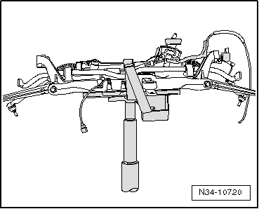
| t | Support bracket -10 - 222 A- |
| t | Adjustment plate -3282/42 A- |
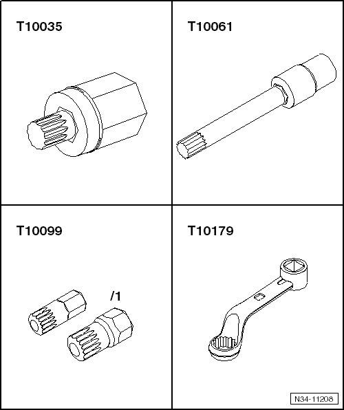
| t | Socket -T10061- |
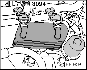
| t | Hose clamps up to 40 mm -3093-, if available, otherwise hose clamps up to 25 mm -3094- |
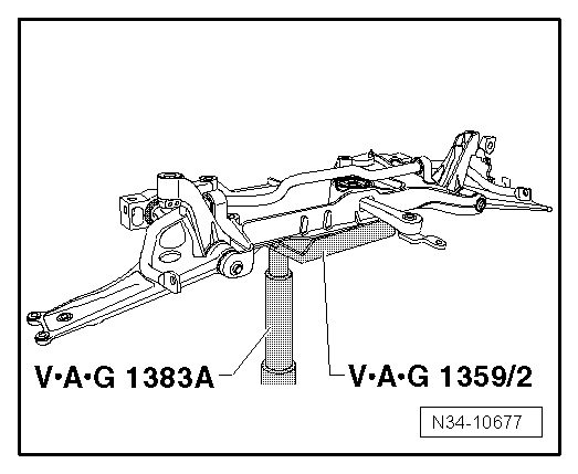
| t | Gearbox support -3282- |
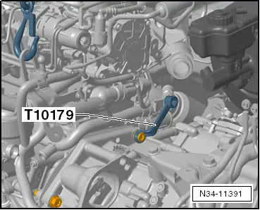
| t | Insert tool, 18 mm -T10179- |
|
|
|
|
|
|
|
|

|
|
|
|
|
|
|
|
|
|
|
|
|
|
|
|
|
|
|
|
|
|
|
|
|

| – | Place support bracket -10 - 222 A- onto upper longitudinal member. |
|
 Caution
|
|
|
|
|
|