
Golf Mk6
| Dismantling and assembling output shaft for 5th, 6th and reverse gears |

| Special tools and workshop equipment required |
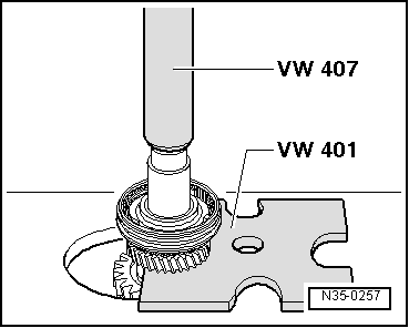
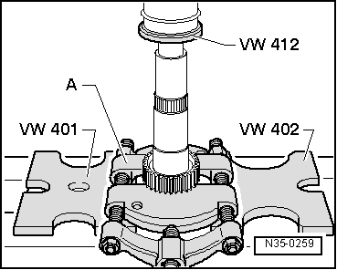
| t | Pressure plate -VW 401- |
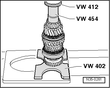
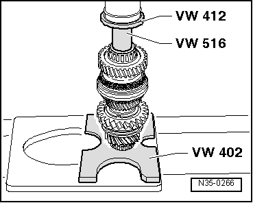
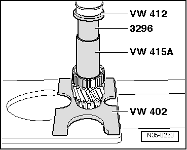
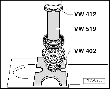
| t | Pressure plate -VW 402- |
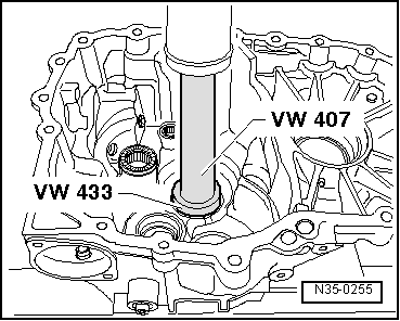
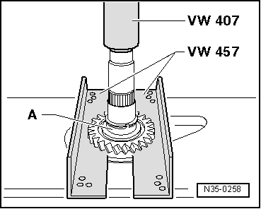
| t | Press tool -VW 407- |
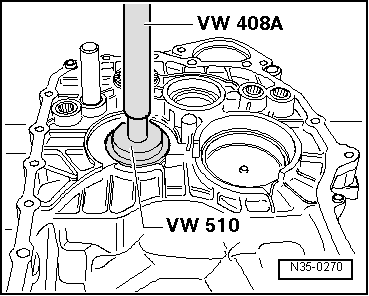
| t | Press tool -VW 408A- |
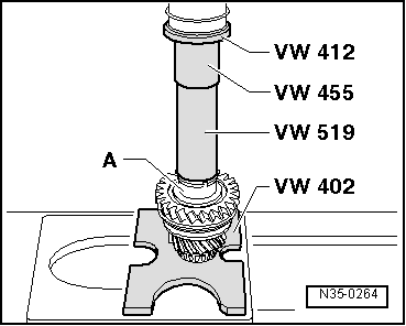
| t | Press tool -VW 412- |
| t | Tube -VW 415A- |

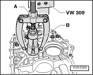
| t | Support plate -VW 309- |
| t | Gearbox support -VW 353- |
| t | Thrust piece -VW 433- |
| t | Thrust piece -VW 454- |
| t | Support rail -VW 457- |
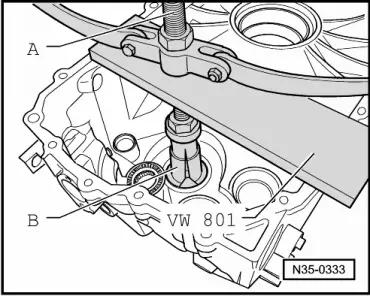
| t | Support plate -VW 801- |

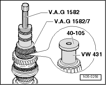
| t | Thrust piece -VW 431- |
| t | Installing sleeve -VW 455- |
| t | Thrust pad -VW 510- |
| t | Tube -VW 516- |
| t | Tube -VW 519- |
| t | Thrust plate -30-11- |

| t | Thrust plate -40-105- |
| t | Drift sleeve -40-20- |
| t | Thrust piece -2050- |
| t | Tube -3296- |
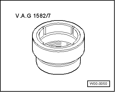
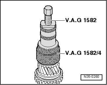
| t | Tapered roller bearing puller -V.A.G 1582- |
| t | Adapter -V.A.G 1582/4- |
|
|
|
|
|
|
|
|
|
|
|
|
|
|
|
|
|
|
| Thickness (mm) | ||
| 1.79 | 1.89 | 1.98 |
| 1.83 | 1.92 | |
| 1.86 | 195 | |
|
|
 Note
Note
|
|
|
|
|
|
|
|
|
|
|
|
|
|
|
|
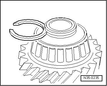
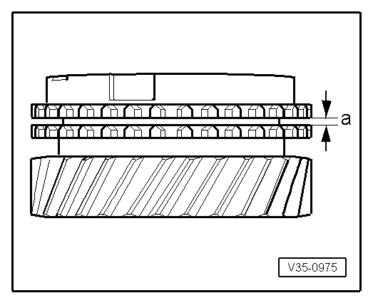
| Gap -a- | Installation dimension | Wear limit |
| 5. and 6th gear | 1.0 … 1.7 mm | 0.5 mm |
|
|
|
|
Note
|
|