| –
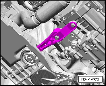
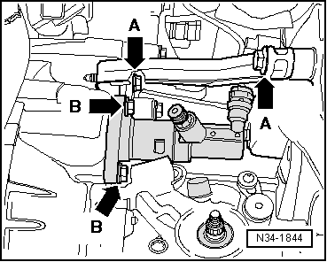
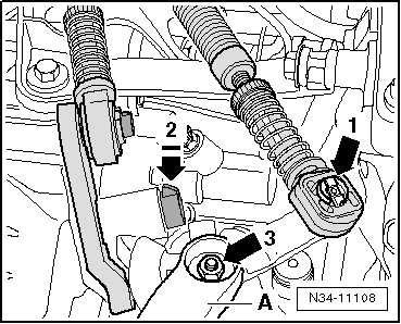
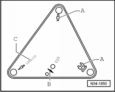
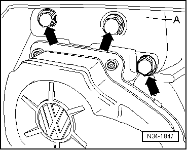
| Install gearbox selector lever -A- → Fig.. |
| –
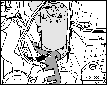
| Tighten hexagon nut -arrow 3- to specified torque → Item. |
| –
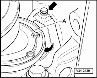
| Spread a small amount of grease on pin of gearbox selector lever -A-. |
| –
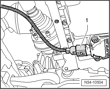
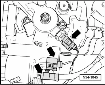
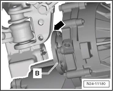
| Connect gear selector cable to gearbox selector lever. |
| –
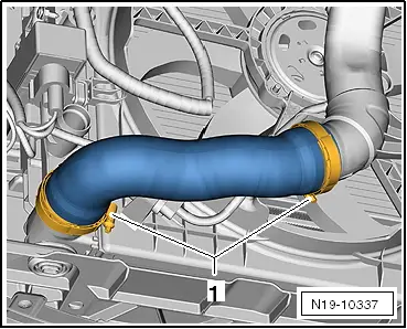
| Renew securing clip -1- each time it is removed. |
| –
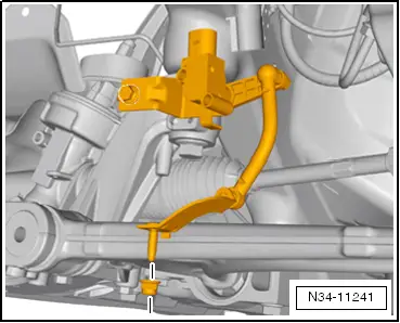
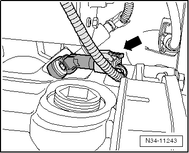
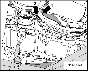
| Insert relay lever together with cable end-piece. |
| l
| Catch -arrow 2- secures relay lever. |
| l
| Ensure proper engagement. |
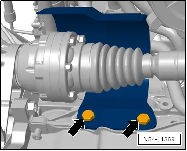
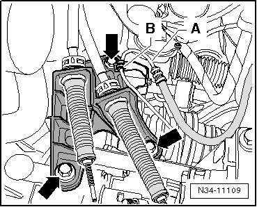
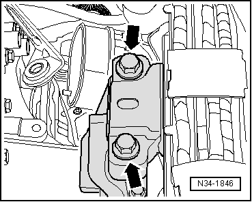
| The relay lever was secured with a clip shortly after start of production → Fig.. |
| Ensure proper engagement of clip. |
| –
| Connect gate selector cable to cable end-piece. |
|
|
|

 Note
Note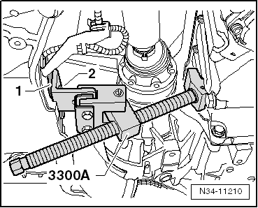
 WARNING