volkswagen Workshop Repair Guides

Volkswagen Workshop Service and Repair Manuals

Specified torques > < Removing gearbox
Installing gearbox
Installing gearbox
  Note
Refer to procedure „Removing gearbox“ for required special tools → Chapter.
–  All threaded holes into which self-locking bolts are to be screwed must be cleaned of residual locking fluid with a thread chaser.
–  Always renew self-locking bolts and nuts.
–  Check whether dowel sleeves for aligning engine and gearbox are fitted in cylinder block and install if necessary.
If dowel sleeves are not fitted, difficulties shifting gears, clutch problems and possible noises from the gearbox (rattling of gears which are not engaged) could occur.
–  Ensure that intermediate plate is correctly seated on engine.
–  Clean input shaft splines and apply thin coat of grease for clutch plate splines -G 000 100-.
The clutch plate must slide easily to and fro on the input shaft.
–  Unbolt right securing bolt for heat shield -1- from subframe.
–  Secure retainer -T10346- with bolt -2-.
-2- = Flange bolt M6 x 20.
–  Secure engine support -3300 A- to bracket -T10346-.
   
–  Place a cloth between engine support -3300 A- and oil pan.
  N34-11210
–  Press engine forwards using spindle of engine support -3300 A-. In the process, observe the following points in particular:
l  The air conditioning compressor -2- must not contact -arrow- the refrigerant line -1-.
l  The alternator must not contact the refrigerant line.
l  The pressure pipe must not contact the radiator.
To install gearbox „0AJ“, set up gearbox support -3282- with adjustment plate -3282/31-.
–  Insert gearbox support -3282- in engine and gearbox jack -V.A.G 1383 A-.
–  Fit adjustment plate -3282/31- on gearbox support -3282- (adjustment plate fits in only one position).
–  Align arms of gearbox support according to holes in adjustment plate.
  A34-10287
–  Screw in support elements-A- to adjustment plate as illustrated.
–  Screw in support hook -3282/49- instead of support element-C-.
–  Place gearbox on engine and gearbox jack.
  N34-1819
–  Insert support hook -3282/49- in one of the recesses in differential below flange shaft -arrow-.
  N34-1830
–  Align adjustment plate and gearbox parallel to one another.
–  Position engine and gearbox jack under vehicle. Arrow -B- on adjustment plate points in direction of vehicle travel.
–  Using spindles of gearbox support -3282-, tilt gearbox in vicinity of 6th gear.
–  Have a second mechanic press engine forwards.
–  Then raise gearbox carefully and guide past subframe.
  Note
Be careful of all lines when installing gearbox.
  N34-1829
–  Carefully guide gearbox with right flange shaft -A- past flywheel -B- and intermediate plate as shown.
  N34-11036
–  Carefully guide left flange shaft -A- past subframe bracket -B- as shown.
–  Turn gearbox to installation position.
l  The gearbox must be aligned parallel to the engine.
  N34-11038
–  Insert gearbox while screwing in bolts -arrows- and tighten to specified torque → Chapter.
  N34-1831
–  Screw in connecting bolt for engine and gearbox -arrow- and tighten to specified torque → Chapter.
  N34-1829
–  Then screw in lower connecting bolts for engine and gearbox -arrows- and tighten to specified torque → Chapter.
–  After all lower connecting bolts for engine and gearbox have been bolted on with specified torque, remove gearbox jack from gearbox.
–  Align engine and gearbox in installation position using spindle of support bracket -10 - 222 A- that is connected to engine.
  N34-1825
–  Install slave cylinder -1- and tighten bolts to specified torque → Item.
–  Press pipe/hose line -A- into retainer -B- on gearbox.
–  Install left assembly mounting -2- using new hexagon bolts -arrows- and tighten to specified torque → Chapter.
  WARNING
Do not remove support bracket -10 - 222 A- until the bolts securing the left and right assembly mountings have been tightened to specified torque.
–  Insert upper engine/gearbox securing bolts and tighten to torque specification.
  N34-1835
–  Install starter with bolt -3- and, if present, nut -2- → Electrical system; Rep. gr.27.
–  Push connector -1- onto reversing light switch -F4-.
  N34-1823
–  Install pendulum support → Running gear, axles, steering; Rep. gr.40.
–  Use new bolts for securing.
  Note
Install engine and gearbox mounting free of tension → Rep. gr.10.
–  Reassemble exhaust system → Rep. gr.26.
–  Push line for lambda probe into retainer for electrical lines on starter and into guides on charge air pipe → Rep. gr.21.
–  Connect wire of lambda probe → Rep. gr.21.
–  Attach drive shafts to gearbox → Running gear, axles, steering; Rep. gr.40.
  N34-10973
–  Attach connector -1- to oil level and oil temperature sender -G266-.
  N34-10504
–  Gearboxes for vehicles with start-stop system: join connector -arrow- to gearbox neutral position sender -G701-.
–  Check for correct installation position of vacuum hose for brake system, install vacuum hose if necessary → Rep. gr.47.
  N34-11273
–  Install cable support bracket on gearbox and tighten bolts -arrows- to specified torque → Item.
  A34-0523
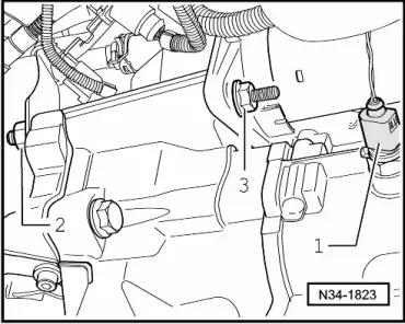
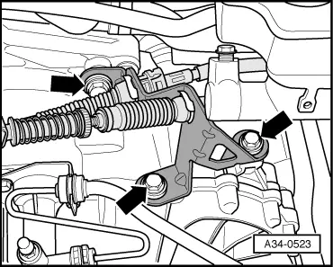
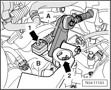
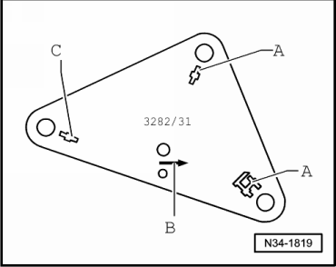
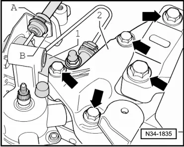
–  Install gearbox selector lever -B- and tighten hexagon nut -arrow 2- to specified torque → Item.
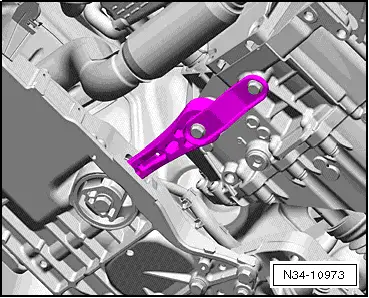
–  Install relay lever -A- together with cable end-piece → Chapter.
–  Spread a small amount of grease on pin of gearbox selector lever -B-.
Allocate grease using → Electronic parts catalogue (ETKA).
–  Connect gear selector cable to gearbox selector lever -arrow 1-.
–  Adjust selector mechanism → Chapter
–  Check gear oil → Chapter.
If the gearbox comes in contact with other components, repair surface protection with manufacturer-approved materials → Paint workshop manual.
–  Install lower part of front left wheel housing liner → General body repairs, exterior; Rep. gr.66.
–  Install noise insulation → General body repairs, exterior; Rep. gr.50.
–  If camshaft housing cover was removed, install it → Rep. gr.15.
–  If removed, reinstall engine cover and air filter housing → Rep. gr.23 or → Rep. gr.24
–  Install battery tray, battery and battery cover → Electrical system; Rep. gr.27.
–  Follow procedure after connecting battery → Electrical system; Rep. gr.27.
  N34-11183

Specified torques > < Removing gearbox