volkswagen Workshop Repair Guides

Volkswagen Workshop Service and Repair Manuals

Removing and installing oil seals at clutch end > < Adjusting position of clutch engagement bearings "K 1" and "K 2"
Installing dual clutch
Special tools and workshop equipment required
   
t  Support device -T10323-
  W00-10386
t  -T10356/5- from assembly tool -T10356-
  W00-10491
t  Puller -T10373-
  W00-10617
t  Thrust piece -T10376-
Installing
  Note
If a further tightening angle is specified for certain bolts, these must be renewed.
  Caution
Risk of damage to clutch and other components!
The positions of the engagement bearings must be set correctly.
Adjustment can only be carried out before the clutch is installed.
The position of the engagement bearings must be adjusted after the following tasks:
t  Clutch has been renewed.
t  Engaging levers were renewed.
t  Retainer of engaging levers was renewed.
t  Engagement bearings were renewed.
If any of the work above has been carried out, you must now adjust the position of engagement bearings „K 1 and K 2“ → Chapter.
Do not continue with assembly until the setting is correct!
If no new parts have been installed, use removed shims.
For adjustment, only one shim per engagement bearing may be installed.
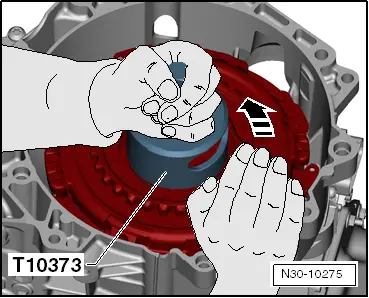
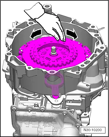
Clutch parts must be free of oil and grease.
  W00-10614
Hinge mounting -1- and ball stud -2- have been installed.
  Note
The upper part of guide sleeve cannot be removed or installed separately. It is always removed and installed together with lower part of guide sleeve and »small« engagement lever.
The following part of the work is only necessary if all the named parts are only removed and then installed again.
  N30-10367
–  Install »small« engagement lever together with upper and lower parts of guide sleeve. Insert and tighten new bolts.
Specified torque: → Anchor
Continuation for all vehicles:
  N30-10389
–  Insert »large« engagement lever with measured shims for „K 1“ and „K 2“ and with small engagement bearing.
  Note
t  The large shim is inserted into the large engagement bearing, with the hemispherical side of the shim facing downwards.
t  The small shim goes under the small engagement bearing. This shim must therefore be inserted first.
  N30-10369
The shim and the small engagement bearing only fit in one position due to the 8 grooves.
–  By turning, check that parts have been installed correctly and that grooves are seated correctly.
–  Check both engaging levers are seated correctly.
–  Turn back spindle of puller -T10373-.
  Caution
Risk of damage from clutch adjustment device.
The clutch is self-adjusting. Shocks can have an effect on this adjusting device. Do not allow clutch to fall into gearbox during installation.
  N30-10370
–  Install clutch with puller -T10373- in gearbox, as shown in diagram.
  N30-10241
–  Position support bracket -T10323- parallel to gearbox flange as shown in illustration.
–  If necessary, balance out gaps using -T10356/5- from assembly tool -T10356-, for example.
–  Screw in bolts -A- hand-tight.
  Note
Bolts -A-, secure with nut as required.
–  Press on clutch as far as it will go.
  Note
Place a hand on the clutch when pressing it on. A slight »rattling« will be felt. Rattling indicates that the clutch is being pressed onto its press seat. This also enables detection of the limit stop once the clutch has been seated correctly.
  N30-10258
–  Take hold of new retaining ring with retaining ring pliers, as shown in the illustration.
l  Installation position: narrow surface of retaining ring on top.
  N30-10172
–  Inserting retaining ring -arrow-.
  Note
If the retaining ring cannot be inserted, the clutch has not been pressed in onto its limit stop.
  N30-10238
–  To ensure that the clutch reaches its operating position right from this stage, turn it against puller -T10373--arrow- by hand without using any other tools.
  Note
t  By pressing on, the clutch sits at the bottom against the limit stop on the input shaft. This is not the optimum position.
  N30-10275
t  Clutch should only be pulled up far enough for it to contact retaining ring.
  Note
Only turn by hand. In this way, clutch slides against retaining ring. Do not use any other tool.
  N30-10293
–  Insert hub.
l  Hub has »large tooth«-arrow- and only fits in one position.
l  »Large tooth« has a mark at engine end.
  N30-10250
–  Insert retaining ring -arrow- of hub.
l  Joint of retaining ring must point towards »hub« of clutch.
  N30-10160
–  Turn clutch by hand. It should be possible to turn it without difficulty.
  Note
t  If the clutch is difficult to turn or if the clutch lining is being rubbed hard, remove clutch again → Chapter.
  N30-10200
t  Check installation position of shims -arrows-.
t  The shims must be properly seated and undamaged → Chapter.
t  A mathematical error could have been made. Check measurements again → Chapter
t  If no error has been made, the clutch may have been moved out of position due to transport/assembly and a new clutch now has to be installed. The position of the engagement bearings must then be readjusted → Chapter.
  N30-10242
–  Remove two plugs and put breather caps -arrows-on.
  WARNING
The breather cap on the mechatronic unit is destroyed during removal and must be renewed.
–  Dispose of excess shims.
–  After installation of gearbox, perform Complete reset by means of Guided functions → Vehicle diagnostic tester.
  N30-10235

Removing and installing oil seals at clutch end > < Adjusting position of clutch engagement bearings "K 1" and "K 2"