volkswagen Workshop Repair Guides

Volkswagen Workshop Service and Repair Manuals

Valve gear > < Removing
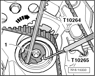
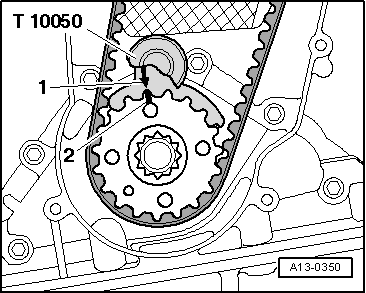
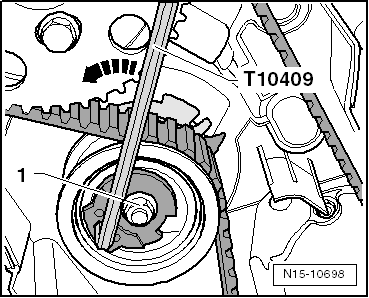
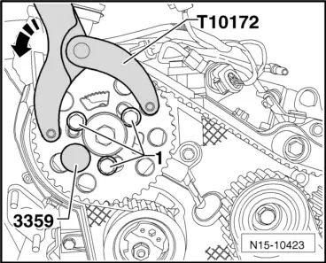
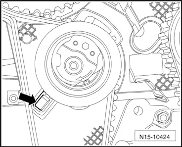
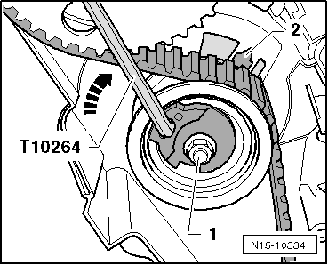
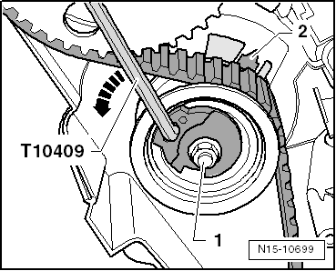
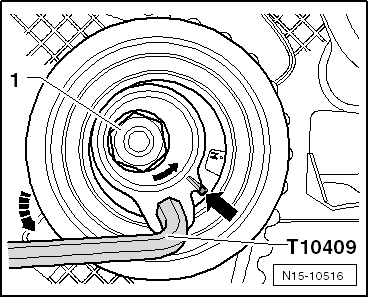
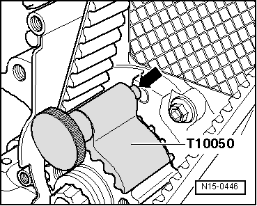
Installing (adjusting valve timing)
  Note
t  The toothed belt may only be adjusted on cold engines, as the indicator position on the tensioning element varies depending on the engine temperature.
t  If the tensioning roller is to be renewed, the engine bracket always has to be removed.
t  Removing and installing engine support (Golf, Passat) → Chapter
t  Removing and installing engine support (Touran) → Chapter
t  Removing and installing engine support (Golf Plus) → Chapter
t  Removing and installing engine support, (Polo) → Chapter
t  
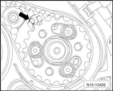
Renew securing bolts for camshaft pulley and high-pressure pump pulley.
Tensioning roller A:
   
l  Tensioning roller must be locked with locking tool -T10265- and secured to right stop.
  N15-10333
l  Crankshaft is locked using crankshaft stop -T10050-.
Tensioning roller B:
  A13-0350
–  Place tensioner for tensioning roller in 9 o'clock position.
–  Secure tensioning roller with 2 - 4 Nm.
  N15-10698
Crankshaft is locked using crankshaft stop -T10050-.
Continuation for both tensioning rollers
  Note
If necessary, turn camshaft hub with counterhold -T10172- and adapters -T10172/4- until camshaft can be secured in position. To do this, hand-tighten at least one securing bolt -1-.
  A13-0350
–  Lock camshaft hub with locking pin -3359-. To do this, slide locking pin through outer free elongated hole into hole in cylinder head.
  N15-10423
–  Loosen bolt which had been tightened only hand-tight.
Loosely tightened bolts -arrows-.
It should just be possible to turn camshaft toothed belt pulley without axial movement.
  Note
If necessary, turn hub of high-pressure pump at bolt heads with screwdriver until it can be secured in position.
  A15-10798
Positioning hub of high-pressure pump
  N15-10427
–  Lock hub of high-pressure pump with locking pin -3359-. To do this, slide locking pin into adjustment hole outside toothed belt pulley.
Loosely tightened bolts -1-.
It should just be possible to turn high-pressure pump toothed belt pulley without axial movement.
  A13-10615
–  Turn camshaft pulley -3- and toothed belt pulley of high-pressure pump -5- in their elongated holes clockwise to stop.
–  Fit toothed belt in sequence described:
1 - Crankshaft toothed belt pulley
2 - Tensioning roller
3 - Camshaft toothed belt pulley
4 - Coolant pump toothed belt pulley
5 - High-pressure pump toothed belt pulley
6 - Idler roller
Tensioning roller A:
–  Loosen tensioning roller securing nut and pull out locking tool -T10265-.
  Note
  A13-10540
Ensure that tensioning roller seats correctly in rear toothed belt guard -arrow-.
  N15-10424
–  Screw eccentric of tensioning roller clockwise carefully using angled screwdriver -T10264-. Indicator -2- must be roughly past the centre of the gap in the base plate (rectifies itself during pretensioning).
Ensure that securing nut -1- does not turn as well.
–  Hold tensioning roller in this position and tighten tensioning roller securing nut as follows: 20 Nm and 45° further.
  N15-10334
–  Apply counterhold -T10172- as shown. Press counterhold -T10172- in direction of arrow, keeping camshaft toothed belt pulley under tension.
–  In this position, first tighten securing bolts -1- of camshaft pulley and of toothed belt pulley for high pressure pump by hand and then tighten to 20 Nm.
Tensioning roller B:
  N15-10423
–  Carefully turn eccentric on tensioning roller counter clockwise using angled screwdriver -T10409-. Indicator -2- must be roughly past the centre of the gap in the base plate (rectifies itself during pretensioning).
  N15-10699
Markings on tensioning element and tensioning roller -arrow- are now almost aligned.
Ensure that securing nut -1- does not turn as well.
–  Hold tensioning roller in this position and tighten tensioning roller securing nut -1-: 20 Nm and turn 45° further.
  N15-10516
–  Apply counterhold -T10172- as shown. Press counterhold -T10172- in direction of arrow, keeping camshaft toothed belt pulley under tension.
  N15-10423
–  Tighten securing bolts -arrows- for camshaft pulley hand-tight at first and then to 20 Nm.
  A15-10798
–  Tighten securing bolts for high-pressure pump toothed belt pulley hand-tight at first and then to 20 Nm.
Continuation for both tensioning rollers
–  Remove locking pins -3359- and crankshaft stop -T10050-.
–  Turn crankshaft at least 2 rotations in engine direction of rotation and set again to TDC no. 1 cylinder.
–  Fit crankshaft stop -T10050- again to crankshaft belt pulley.
  A13-10615
–  Now turn crankshaft in engine direction of rotation until pin of crankshaft stop -arrow- engages in sealing flange from rotational movement.
  Note
  N15-0446
During the following checking procedure, only the camshaft and crankshaft must be secured in position. It is very difficult to find the securing position of the high-pressure pump hub again. However, a slight deviation -arrow- does not influence the engine operation.
–  Check if:
t  Camshaft hub can be locked with locking pin -3359-.
t  Tensioning roller indicator is centred or maximum 5 mm to right of base plate notch.
If camshaft hub cannot be locked:
–  Pull crankshaft stop -T10050- back until pin uncovers hole.
–  Turn crankshaft in opposite direction of engine rotation slightly past TDC.
–  Now turn crankshaft slowly in direction of engine rotation until camshaft hub can be secured in position.
–  After locking, loosen securing nuts of crankshaft toothed belt pulley.
If pin of crankshaft stop -T10050- is standing on left next to hole:
  N15-10426
–  Turn crankshaft in engine direction of rotation until crankshaft stop pin engages in sealing flange whilst turning.
–  Tighten securing bolts of camshaft toothed belt pulley by hand first and then tighten to 20 Nm.
If pin of crankshaft stop -T10050- is standing on right next to hole:
–  Slightly turn crankshaft in opposite direction of engine rotation.
–  Now turn crankshaft in engine direction of rotation until crankshaft stop pin engages in sealing flange whilst turning.
–  Tighten securing bolts of camshaft toothed belt pulley by hand first and then tighten to 20 Nm.
Continuation
–  Remove locking pin -3359- and crankshaft stop -T10050-.
–  Turn crankshaft at least 2 rotations in engine direction of rotation and set again to TDC no. 1 cylinder.
–  Repeat check.
–  If camshaft hub can be secured in position, tighten securing bolts as follows:
  N15-0446
t  Camshaft toothed belt pulley: turn 45° further. Counterhold with counterhold -T10172- and adapters -T10172/4-.
  N15-10423
t  Counterhold high-pressure pump toothed belt pulley with counterhold -T10172- and adapters -T10172/8-. 20 Nm, do not turn any further.
–  Install centre and lower parts of toothed belt guard.
–  Install belt pulley vibration damper: specified torque 10 Nm + 90° further.
–  Install poly V-belt.
–  Install upper toothed belt guard.
Further assembly is basically the reverse of the dismantling sequence. In the process, note the following:
t  Ensure that fuel hose connections are tight.
t  Do not interchange supply line and return line (return line blue or with blue marking, supply line white).
–  Install wheel housing liner.
–  Install noise insulation. → General body repairs, exterior; Rep. gr.50.
  N15-10425

Valve gear > < Removing