volkswagen Workshop Repair Guides

Volkswagen Workshop Service and Repair Manuals

Valve gear > < Assembly overview - toothed belt
Removing and installing toothed belt
   
Removing and installing toothed belt
Special tools and workshop equipment required
t  Locking pin -3359-
t  Crankshaft stop -T10050-
t  Counterhold tool -T10172-
t  Special wrench, long reach -T10264-
t  Locking tool -T10265-

Not illustrated:
t  Torque wrench -V.A.G 1331-
t  Torque wrench -V.A.G 1332-
Removing
  Note
The toothed belt may only be adjusted on cold engines, as the indicator position on the tensioning element varies depending on the engine temperature.
–  Remove engine cover panel → Chapter.
–  Remove fuel filter → Fuel supply - Diesel engines; Rep. gr.20.
–  Remove supplementary fuel pump -V393- or fuel pump 2 -V277- → Fuel supply - Diesel engines; Rep. gr.20.
   
–  Pull connector off radiator outlet coolant temperature sender -G83-, open clips -arrows- and remove toothed belt guard.
–  Remove front right wheel housing liner → General body repairs, exterior; Rep. gr.66
–  Remove poly V-belt → Chapter.
–  Remove vibration damper → Item.
  N15-10405
–  Remove lower and centre toothed belt guard -arrows- and unscrew securing nut of coolant pipe -1-.
  N15-10399
–  Turn engine to upper TDC and pin crankshaft toothed belt pulley with crankshaft stop -T10050-. To do this, push crankshaft stop into toothed belt pulley splines from face end. The toothed segment of the camshaft must be at the »12 o'clock position«.
  Note
The markings on the crankshaft toothed belt pulley -2- and the crankshaft stop -T10050--1- must align. At the same time, the pin of the crankshaft stop -T10050- must engage in the drilling in the sealing flange.
–  Mark direction of rotation of toothed belt.
  A13-0350
–  Loosen securing bolts -1- for camshaft toothed belt pulley.
  N15-0232
–  Loosen securing bolt of coolant pipe -1- and then securing bolts of toothed belt pulley for high-pressure pump -2-.
–  Loosen tensioning roller securing nut -1-.
  N15-10400
–  Turn eccentric of tensioning roller anti-clockwise -arrow- using socket -T10264-, until the tensioning roller can be locked with locking tool -T10265-.
  N15-10332
–  Now turn tensioning roller eccentric clockwise -arrow- onto stop and tighten securing nut -1- hand-tight.
–  Remove toothed belt first from idler roller and then from remaining pulleys.
Installing
  Note
t  The toothed belt may only be adjusted on cold engines, as the indicator position on the tensioning element varies depending on the engine temperature.
t  If the tensioning roller is to be renewed, the engine bracket must be removed → Chapter.
t  Renew securing bolts for camshaft pulley and high-pressure pump pulley.
l  Tensioning roller must be locked with locking tool -T10265- and secured to right stop.
l  Crankshaft is locked using crankshaft stop -T10050-.
  Note
If necessary, turn camshaft hub with counterhold -T10172- and adapters -T10172/4- until camshaft can be secured in position. To do this, hand-tighten at least one securing bolt -1-.
  N15-10333
–  Lock camshaft hub with locking pin -3359-. To do this, slide locking pin through outer free elongated hole into hole in cylinder head.
–  Loosen bolts which had been tightened only hand-tight.
  Note
If necessary, turn hub of high-pressure pump at bolt heads with screwdriver until it can be secured in position.
  N15-10423
Positioning hub of high-pressure pump
  N15-10427
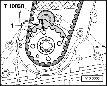
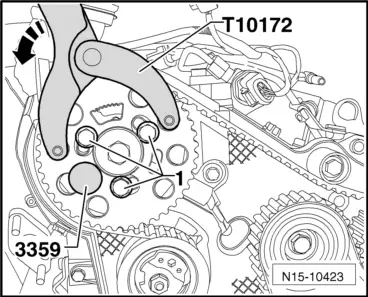
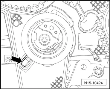
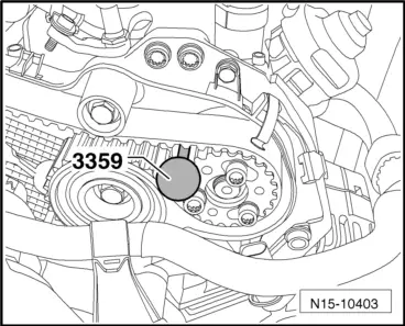
–  Lock hub of high-pressure pump with locking pin -3359-. To do this, slide locking pin into adjustment hole outside toothed belt pulley.
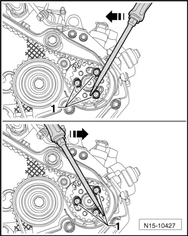
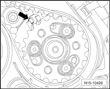
–  Turn camshaft pulley and toothed belt pulley of high-pressure pump in their elongated holes clockwise to stop.
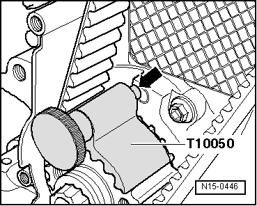
–  Fit toothed belt to crankshaft toothed belt pulley, tensioning roller, camshaft pulley, toothed belt pulley of coolant pump and toothed belt pulley of high-pressure pump.
–  Finally, fit toothed belt to idler roller.
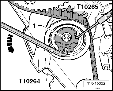
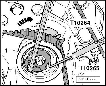
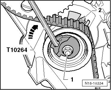
–  Loosen tensioning roller securing nut and pull out locking tool -T10265-.
  Note
  N15-10403
Ensure that tensioning roller seats correctly in rear toothed belt guard -arrow-.
  N15-10424
–  Screw eccentric of tensioning roller clockwise carefully using angled screwdriver -T10264-. Indicator -2- must be roughly past the centre of the gap in the base plate (rectifies itself during pretensioning).
Ensure that securing nut -1- does not turn as well.
–  Hold tensioning roller in this position and tighten tensioning roller securing nut as follows: 20 Nm and 45° further.
  N15-10334
–  Apply counterhold -T10172- as shown. Press counterhold -T10172- in direction of arrow, keeping camshaft toothed belt pulley under tension.
–  In this position, first tighten securing bolts -1- of camshaft pulley and of toothed belt pulley for high pressure pump by hand and then tighten to 20 Nm.
–  Remove locking pins -3359- and crankshaft stop -T10050-.
–  Turn crankshaft at least 2 rotations in engine direction of rotation and set again to TDC no. 1 cylinder.
–  Fit crankshaft stop -T10050- again to crankshaft belt pulley.
  N15-10423
–  Now turn crankshaft in engine direction of rotation until pin of crankshaft stop -arrow- engages in sealing flange from rotational movement.
  Note
  N15-0446
During the following checking procedure, only the camshaft and crankshaft must be secured in position. It is very difficult to find the securing position of the high-pressure pump hub again. However, a slight deviation -arrow- does not influence the engine operation.
–  Check whether:
t  Camshaft hub can be locked with locking pin -3359-.
t  Tensioning roller indicator is centred or maximum 5 mm to right of base plate notch.
If camshaft hub cannot be locked:
–  Pull crankshaft stop -T10050- back until pin uncovers hole.
–  Turn crankshaft in opposite direction of engine rotation slightly past TDC.
–  Now turn crankshaft slowly in direction of engine rotation until camshaft hub can be secured in position.
–  After locking, loosen securing nuts of crankshaft toothed belt pulley.
If pin of crankshaft stop -T10050- is standing on left next to hole:
  N15-10426
–  Turn crankshaft in engine direction of rotation until crankshaft stop pin engages in sealing flange whilst turning.
–  Tighten securing bolts of camshaft toothed belt pulley by hand first and then tighten to 20 Nm.
If pin of crankshaft stop -T10050- is standing on right next to hole:
–  Slightly turn crankshaft in opposite direction of engine rotation.
–  Now turn crankshaft in engine direction of rotation until crankshaft stop pin engages in sealing flange whilst turning.
–  Tighten securing bolts of camshaft toothed belt pulley by hand first and then tighten to 20 Nm.
Continuation
–  Remove locking pin -3359- and crankshaft stop -T10050-.
–  Turn crankshaft at least 2 rotations in engine direction of rotation and set again to TDC no. 1 cylinder.
–  Repeat check.
–  If camshaft hub can be secured in position, tighten securing bolts as follows:
t  Camshaft sprocket: 45° further. Counterhold with counterhold -T10172- and adapters -T10172/4-.
  N15-0446
t  High pressure pump sprocket: 90° further. Counterhold with counterhold -T10172- and adapters -T10172/8-.
–  Install centre and lower parts of toothed belt guard.
–  Install belt pulley vibration damper: specified torque 10 Nm + 90° further.
–  Install poly V-belt → Chapter.
–  Install upper toothed belt guard.
Further assembly is basically the reverse of the dismantling sequence. In the process, note the following:
t  Ensure that fuel hose connections are tight.
t  Do not interchange fuel supply and return lines (return line is blue or with blue markings and supply line is white).
–  Install wheel housing liner.
–  Install noise insulation. → General body repairs, exterior; Rep. gr.66.
  N15-10425

Valve gear > < Assembly overview - toothed belt