Golf Mk6
| Assembly overview - balancer shaft module |
 Caution
|

| 1 - | Oil sump |
| q | Removing and installing → Chapter. |
| 2 - | 10 Nm |
| 3 - | Intake connecting pipe |
| q | Clean strainer if soiled. |
| 4 - | 10 Nm |
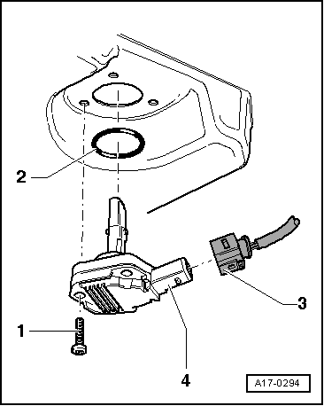
| 5 - | O-ring |
| q | Renew. |
| 6 - | Oil pump |
| q | Removing and installing → Chapter. |
| q | Before installing, check that the two dowel sleeves for centring oil pump on balancer shaft module are fitted. |
| 7 - | Drive shaft for oil pump |
| 8 - | Circlip |
| q | Must lie in base of groove. |
| q | Renew damaged or over-tensioned circlip. |
| 9 - | Spur gear for balancer shaft |
| 10 - | 20 Nm + turn 90° further |
| q | Renew. |
| 11 - | Hub |
| q | For intermediate gear wheel. |
| q | Renew. |
| 12 - | 90 Nm + turn 90° further |
| q | Renew. |
| 13 - | Thrust washer |
| q | For intermediate gear wheel. |
| q | Renew. |
| q | Note installation position → Fig.. |
| 14 - | Intermediate gear wheel |
| q | Renew. |
| q | A coating is applied to the new intermediate gear wheel which sets the correct tooth backlash through wear. |
Caution
|
| q | Installation position: Part number must be visible. |
| q | Installing → Chapter. |
| 15 - | Thrust washer |
| q | For intermediate gear wheel. |
| q | Renew. |
| q | Note installation position → Fig.. |
| q | If necessary, attach to housing with grease when installing intermediate gear wheel |
| 16 - | Spur gear for crankshaft |
| q | Renew if signs of wear are found → Chapter |
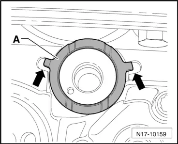
| 17 - | Balancer shaft module |
| q | Removing → Chapter |
| q | Installing new balancer shaft module → Chapter. |
| q | Reinstalling previously run balancer shaft module → Chapter. |
| q | Before installing, check that the two dowel sleeves for centring balancer shaft module on cylinder block are fitted. |
| 18 - | M7 = 13 Nm + 90° further; M8 = 20 Nm + 90° further |
| q | Renew. |
| q | Note tightening sequence: installing new balancer shaft module → Chapter, reinstalling previously run balancer shaft module → Chapter. |
| 19 - | Oil extraction pipe |
| 20 - | 10 Nm |
| 21 - | 40 Nm |
| 22 - | 45 Nm |
| 23 - | 15 Nm |
| q | Tighten in stages and in diagonal sequence. |
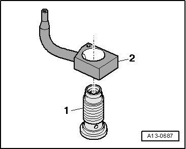
| 24 - | Seal |
| q | Permanently attached to drain plug |
| 25 - | Oil drain plug, 30 Nm |
| q | With seal. |
| q | Renew. |
|
|
|
|