
Golf Mk6
| Assembly overview - valve gear |
 Caution
|
 Note
Note| Cylinder heads with cracks between the valve seats may continue to be used without reducing engine life, provided the cracks are small and not more than 0.5 mm wide. |

| 1 - | Valve |
| q | Do not rework. Only lapping in is permitted. |
| q | Mark installation position for re-installation. |
| q | Checking → Chapter. |
| q | Valve dimensions → Chapter. |
| q | Checking valve guides → Chapter. |
| 2 - | Cylinder head |
| 3 - | Valve stem seal |
| q | Renewing with cylinder head installed → Chapter. |
| q | Renewing with cylinder head removed → Chapter. |
| 4 - | Valve spring |
| 5 - | Valve spring plate |
| 6 - | Valve cotters |
| 7 - | Cap |
| q | Renew. |
| q | Removing: With retaining frame installed, pierce one side of cap with an awl and pry out. |
| q | Installing: Drive in without sealant using an appropriate thrust piece. |
| q | Insertion depth 1 … 2 mm. |
| 8 - | Oil seal |
| q | Renewing → Chapter. |
| 9 - | Exhaust camshaft |
| q | Removing and installing → Chapter. |
| q | Measuring axial clearance → Chapter. |
| q | Measuring radial clearance → Chapter |
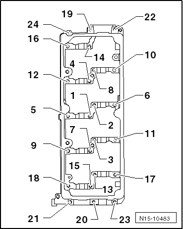
| 10 - | Bolt |
| q | Specified torque and tightening sequence → Fig.. |
| 11 - | Retaining frame |
| q | With integrated camshaft bearings. |
| q | Specified torque and tightening sequence → Fig.. |
| 12 - | Inlet camshaft |
| q | Removing and installing → Chapter. |
| q | Measuring axial clearance → Chapter. |
| q | Measuring radial clearance → Chapter |
| 13 - | Roller rocker finger |
| q | Mark installation position for re-installation. |
| q | Check roller bearing for ease of movement. |
| q | Lubricate contact surfaces before installing. |
| 14 - | Securing clip |
| q | For hydraulic compensation element. |
| 15 - | Hydraulic compensation element |
| q | Mark installation position for re-installation. |
| q | Lubricate contact surfaces before installing. |
|
|
| Stage | Bolts | Specified torque | ||
| 1. | -1 … 24- | Screw in to contact by hand
| ||
| 2. | -1 … 24- | 10 Nm |