Golf Mk6 Diesel Engine Lubrication: Oil Pump/Sump Overview
| Assembly overview - oil pump/sump, engine codes CFFA, CFFB, CFGB, CFFD, CLLA, CLJA |
 Note
Note| t | Oil capacities, oil specifications, viscosity grades → Maintenance tables. |
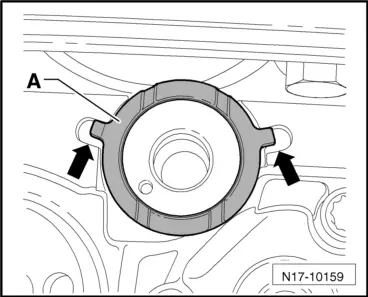
| t | Oil spray jet and pressure relief valve → Fig. |
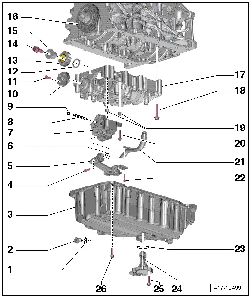
| 1 - | Seal |
| q | Permanently attached to drain plug. |
| 2 - | Oil drain plug, 30 Nm |
| 3 - | Oil sump |
| q | Removing and installing → Chapter |
| 4 - | 9 Nm |
| 5 - | Suction line |
| q | Clean strainer if soiled. |
| 6 - | O-ring |
| q | Renew. |
| 7 - | Oil pump |
| q | Removing and installing → Chapter. |
| q | Before installing, check that the two dowel sleeves for centring oil pump on balancer shaft module are fitted. |
| 8 - | Drive shaft |
| q | For oil pump. |
| 9 - | Circlip |
| q | Must lie in base of groove. |
| q | Renew damaged or over-tensioned circlip. |
| 10 - | Spur gear |
| q | For balancer shaft. |
| 11 - | 20 Nm + turn 90° further |
| q | Renew. |
| 12 - | Thrust washer |
| q | For intermediate gear wheel. |
| q | Renew. |
| q | Installation position → Fig.. |
| q | To install intermediate gear wheel, secure to balancer shaft module with grease. |
| 13 - | Intermediate gear wheel |
| q | Renew. |
| q | A coating is applied to the new intermediate gear wheel which sets the correct tooth backlash through wear. |
| q | Installation position: Part number must be visible. |
| q | Make sure thrust washer is seated correctly → Fig.. |
| 14 - | 90 Nm + 90° |
| q | With washer. |
| q | Renew. |
| 15 - | Hub |
| q | For intermediate gear wheel. |
| q | Renew. |
| 16 - | Crankshaft sprocket |
| 17 - | Balancer shaft module |
| q | Removing → Chapter |
| q | Reinstalling previously run balancer shaft module → Chapter. |
| q | Installing new balancer shaft module → Chapter. |
| q | Before installing, check that the two dowel sleeves for centring balancer shaft module on cylinder block are fitted. |
| 18 - | M7 = 13 Nm + 90° further; M8 = 20 Nm + 90° further |
| q | Renew. |
| q | Note tightening sequence: installing new balancer shaft module → Chapter, reinstalling previously run balancer shaft module → Chapter. |
| 19 - | Dowel sleeves |
| 20 - | 9 Nm |
| 21 - | Oil extraction pipe |
| 22 - | 9 Nm |
| 23 - | Seal |
| q | Renew. |
| 24 - | Oil level and oil temperature sender -G266- |
| q | Removing and installing → Chapter |
| 25 - | 9 Nm |
| q | Self-locking. |
| q | Renew. |
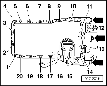
| 26 - | Bolt |
| q | Renew. |
| q | Specified torque and tightening sequence → Fig.. |
Note
|
|
| Stage | Bolts | Specified torque |
| 1. | -1 … 20- | in diagonal sequence, 5 Nm |
| 2. | -arrows- | 40 Nm |
| 3. | -1 … 20- | in diagonal sequence and in stages; final torque 15 Nm |
 Caution