volkswagen Workshop Repair Guides

Volkswagen Workshop Service and Repair Manuals

Renewing vacuum unit for turbocharger > < Assembly overview - turbocharger
Removing and installing turbocharger
Special tools and workshop equipment required
   
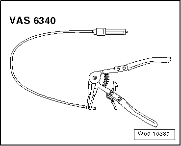
t  Hose clip pliers -VAS 6340-
Removing
  Note
Fit heat shield sleeve in the same place when installing.
–  Observe rules for cleanliness → Chapter.
  Caution
If a mechanical fault is discovered on the turbocharger (e.g. a destroyed compressor impeller), it is not sufficient to just renew the turbocharger. To avoid any subsequent damage, the following work must be carried out:
t  Check air filter housing, air filter element and air inlet hoses for contamination.
t  Check the whole charge air path and charge air cooler for foreign objects.
t  If foreign objects are discovered in the charge air system, clean the charge air path and, if necessary, renew the charge air cooler.
–  Remove particulate filter → Chapter.
–  Remove air filter housing → Chapter.
  W00-10380
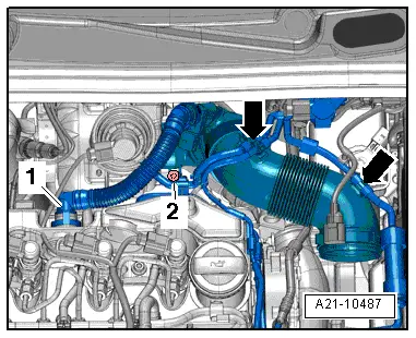
–  Remove crankcase breather hose -1- from cylinder head cover. Do this by operating release buttons.
–  Expose vacuum hoses -arrows- at air pipe.
–  Unscrew bolt -2-, swing air pipe with inlet connection to rear and pull off from turbocharger.
  A21-10487
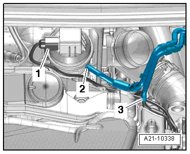
–  Remove heat-shield sleeve.
–  Pull vacuum hose -2- from turbocharger vacuum unit.
–  Separate vacuum hose -3-.
–  Disconnect electrical connector -1- at position sender for charge pressure positioner -G581-.
  A21-10338
–  Free electrical connector -3- for exhaust temperature sender 1 -G235- and electrical line.
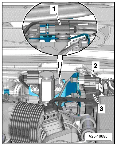
  A26-10696
–  Remove bolts -arrows-.
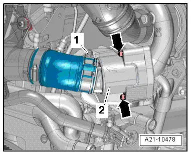
–  Undo hose clip -1- and remove the pulsation damper -2-.
  A21-10478
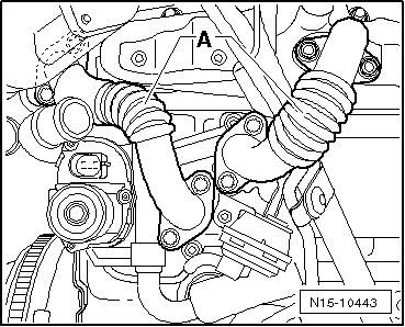
–  Unscrew bolts and remove pipes -A- for exhaust gas recirculation.
–  In vehicles with an auxiliary heater, remove the brackets for the coolant lines leading to the auxiliary heater from the cylinder block or transfer gearbox and the oil sump.
Front-wheel drive vehicles
  N15-10443
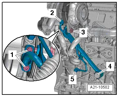
–  Unscrew bolts -1, 3-, union nut -2- and banjo bolts -4, 5-, and remove turbocharger support with oil supply line.
Vehicles with four-wheel drive
–  Remove right drive shaft → Running gear, axles, steering; Rep. gr.40.
–  Pull right flange shaft from bevel box → final drive, axle differential; Rep. gr.39.
  A21-10502
–  Unscrew hollow bolts -4- and bolts -1- and -3-.
–  Open connecting clamp for oil supply line, disconnect and remove support from the oil supply line.
  A21-10502
–  Remove oil supply line -2- on turbocharger.
Continuation for all vehicles
  A21-10502
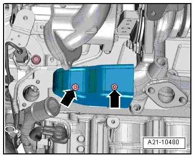
–  Unscrew bolts -arrows- and remove heat shield.
  A21-10480
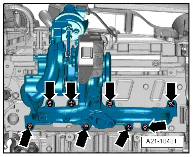
–  Remove nuts -arrows-.
–  Remove turbocharger together with exhaust manifold from cylinder head and turn so that intake side is facing downwards. Remove turbocharger together with exhaust manifold downwards.
Installing
l  Specified torques → Chapter „Assembly overview - turbocharger“.
Installation is carried out in the reverse order; note the following:
  Note
t  Renew seals, gaskets, O-rings and self-locking nuts.
t  Fill turbocharger with engine oil at connection for oil supply line.
t  Hose connections and air intake pipes/hoses must be free of oil and grease when installing.
t  Secure hose connections with hose clips corresponding to the series equipment → Electronic parts catalogue.
t  After installing turbocharger, run engine for about 1 minute at idling speed to ensure that oil is supplied to turbocharger.
t  Fit heat shield sleeves in the same place when installing turbocharger.
–  Installing intake hoses with screw-type clips → Fig..
–  Install exhaust gas recirculation pipes → Chapter.
–  Connect vacuum hoses → Chapter.
–  Electrical connections and routing → Current flow diagrams, Electrical fault finding and Fitting locations.
–  Install air filter housing → Chapter.
–  Install particulate filter → Chapter.
  A21-10481

Renewing vacuum unit for turbocharger > < Assembly overview - turbocharger