| –
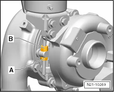
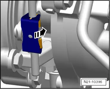
| Press locking plate by hand onto the control rod and, if possible, turn 90° in the -direction of the arrow-. |
| –
| Seal connection between control rod and securing nut with sealing paint from the spare-parts kit. |
| –
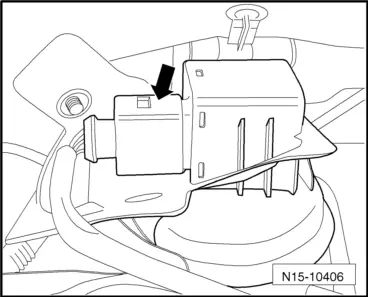
| Remove sealing cap from turbocharger. |
| –
| Check setting as follows: |
| Select diagnostic function: |
| –
| Click the „006 - Basic setting“ button on the display. |
| –
| Select „Adaption of turbocharger“ from selection list. |
| –
| Click the „Measured values“ button on the bottom right on the display. |
| –
| Select „Positioner for high pressure turbocharger, actual raw voltage“ from selection list. |
| –
| Click the „Start“ button on the bottom right on the display. |
| –
| Observe the value in the lower screen window; it must fluctuate between 650 ... 850 mV and 3,000 ... 3,400 mV (vacuum unit is move to both end stops alternately). |
| –
| End basic setting procedure. |
|
|
|
 Note
Note
 Caution