volkswagen Workshop Repair Guides

Volkswagen Workshop Service and Repair Manuals

Removing and installing camshaft > < Removing and installing cylinder head cover and camshaft
Removing cylinder head cover
–  Release pressure in high-pressure area → Chapter.
  WARNING
The injection system consists of a high-pressure section (maximum approx. 120 bar) and a low-pressure section (approx. 6 bar).
Prior to opening the high-pressure area, the fuel pressure in the high-pressure area must be reduced to a residual pressure of approx. 6 bar. The appropriate procedure is described in the chapter on releasing pressure in the high-pressure section → Chapter.
–  With ignition switched off, disconnect battery earth strap.
–  Drain coolant → Chapter.
   
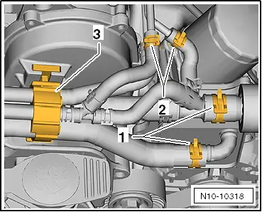
–  Open spring-type clips and pull coolant hoses -1- and -2- off.
–  Push catch -3- underneath coolant hoses and pull hoses upwards.
–  Put down coolant hoses to rear.
  N10-10318
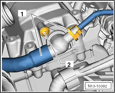
–  Pull both hoses -1- off non-return valve.
–  Unscrew securing bolt -2- and pull non-return valve out of cylinder head cover.
  N13-10382
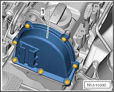
–  Remove all securing bolts from valve timing housing cover -1-.
–  Remove valve timing housing cover.
  N13-10390
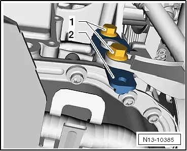
–  Remove securing bolts -1- and remove coolant pipe bracket -2-.
  N13-10385
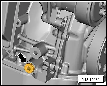
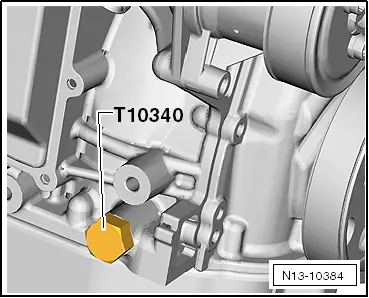
–  Unscrew plug -arrow- from cylinder block.
–  Screw locking pin -T10340- to stop into crankcase.
–  Turn crankshaft in normal direction of rotation until the stop.
  Caution
If locking pin -T10340- cannot be screwed in as far as stop, this indicates that crankshaft is not in the correct position!
In this case, proceed as described below.
–  Remove locking pin.
–  Turn crankshaft 1/4 revolution (90°) in normal direction of rotation.
–  Screw locking pin -T10340- to stop into crankcase.
–  Tighten locking pin -T10340- to 30 Nm.
–  Turn crankshaft in normal direction of rotation until the stop.
  N13-10383
Locking pin -T10340- locks crankshaft in direction of engine rotation.
  N13-10384
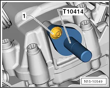
–  Insert locking pin -T10414- to stop in cylinder head cover.
–  Tighten securing bolt -1- hand tight.
  Caution
Sump only needs to be removed on vehicles ► 12.2009.
In these vehicles, the timing chain can slip off the crankshaft chain sprocket during installation!
–  Remove sump → Chapter.
  N15-10549
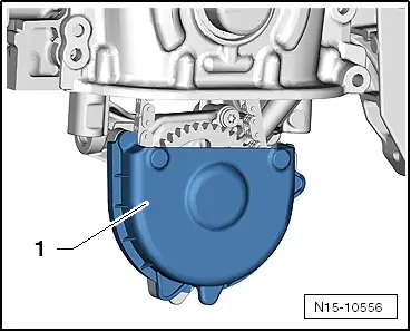
–  Pull cover -1- off oil pump.
All vehicles
  N15-10556
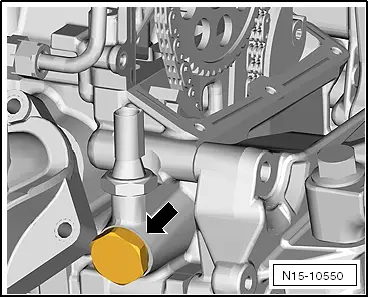
–  Unscrew chain tensioner -arrow- for timing chain.
  N15-10550
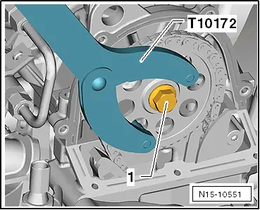
–  Loosen securing bolt -1- for camshaft chain sprocket.
–  Hold camshaft chain sprocket with counterhold tool -T10172-.
–  Remove camshaft sprocket together with securing bolt.
  N15-10551
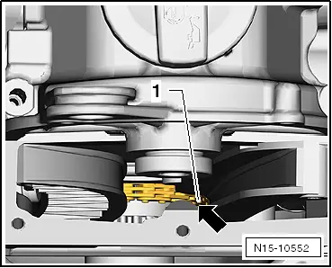
–  Place timing chain -1- on cast lug -arrow- in valve timing housing.
  Note
Cast lug on inside of valve timing housing prevents timing chain from falling down.
–  Unscrew bolts -1- and remove retaining clip.
  N15-10552
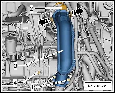
–  Pull connector -2- off charge air pressure sender -G31-.
–  Unlock catches in -direction of arrow- and pull pressure pipe -3- first off throttle valve module -J338- and then off turbocharger.
–  Open cover -4- and remove securing bolt.
–  Use puller -T10112 A- to pull all spark plug connectors off spark plugs and put down ignition cables towards the rear.
  N15-10561
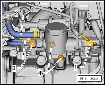
–  Pull connector -1- and fuel supply line -2- off high-pressure pump.
  Caution
Only grasp high-pressure pump on housing when removing and installing!
When the high-pressure piston spring package loosens the high-pressure pump will leak and must be replaced.
–  Loosen union nuts -3- and remove line.
–  Counterhold on bolted connections with an open-end spanner.
–  Remove securing bolts from high-pressure pump and pull it out of cylinder head cover using tappet.
–  Pull connector off injectors.
  N15-10562
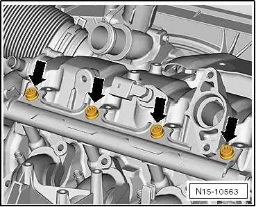
–  Remove bolts -arrows- and pull fuel rail off injectors.
–  Remove turbocharger → Chapter.
–  Disconnect connector off Hall sender -G40-.
–  Pull out oil dipstick.
–  Loosen cylinder head cover securing bolts from outside to inside, alternately and diagonally and remove.
–  Carefully remove cylinder head cover.
–  Remove sealant residues from cylinder head and cylinder head cover with a rotating brush, e.g. a hand drill with a plastic brush (wear eye protection).
–  Clean sealing surfaces carefully. They must be free of oil and grease.
–  Also prevent dirt and residual sealant from entering cylinder head.
Removing and installing camshaft → Chapter.
Fitting the cylinder head cover → Chapter
  N15-10563

Removing and installing camshaft > < Removing and installing cylinder head cover and camshaft