volkswagen Workshop Repair Guides

Volkswagen Workshop Service and Repair Manuals

Securing engine to assembly stand > < Removing and installing engine (Golf, Golf Plus, Eos, Scirocco)
Removing engine
   
Removing engine
Special tools and workshop equipment required
t  Engine support -T40075- with adapters /1, /2, /3
t  Torque wrench (5…50 Nm) -V.A.G 1331-
t  Engine and gearbox jack -V.A.G 1383 A-
t  Engine and gearbox support -VAS 6095-
t  Drip tray for workshop hoist -VAS 6208-

   
t  Hose clip pliers -VAS 6340-
t  Stepladder -VAS 5085-
t  Torque wrench (40…200 Nm) -V.A.G. 1332-
t  Guide rods -T10093-

  Note
Before carrying out further work, disconnect battery earth strap. Check whether a coded radio is fitted. Obtain anti-theft coding first if necessary.
   
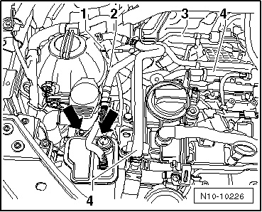
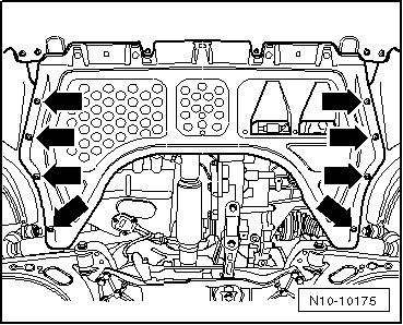
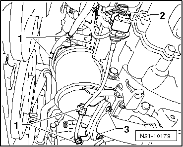
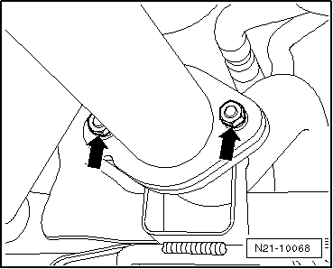
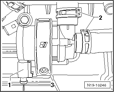
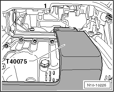
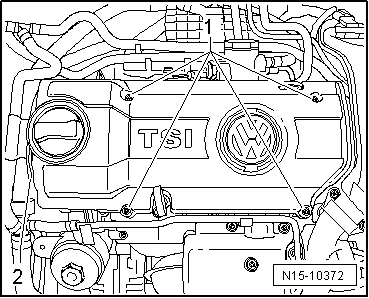
–  Remove securing bolts -1- from engine cover panel.
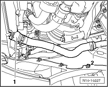
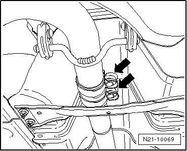
–  Detach coolant hoses -2- at engine cover panel and pull engine cover panel upwards.
–  Remove air filter → Chapter.
–  Open and close expansion tank cap to release pressure in cooling system.
–  Drain coolant → Chapter.
–  Observe rules for cleanliness → Chapter.
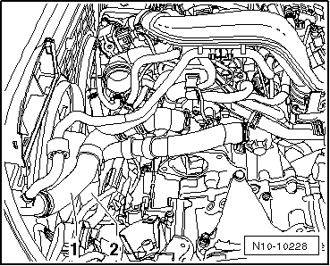
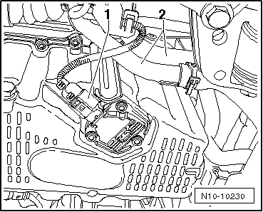
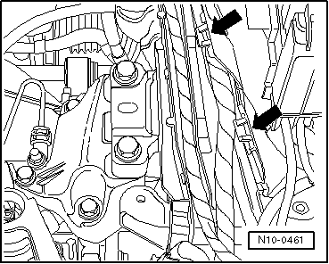
–  Separate fuel supply line -1- and line to activated charcoal filter -2-.
–  Separate push-on couplings → Chapter.
  WARNING
Fuel supply lines are under pressure! Wear eye protection and gloves to avoid injuries and skin contact. Before loosening hose connections, wrap a cloth around the connection. Then release pressure by carefully pulling hose off connection.
Golf, Golf Plus, Eos, Scirocco
  N15-10372
–  Remove hose -3- from activated charcoal filter system solenoid valve 1 -N80- to activated charcoal filter.
–  Pull activated charcoal filter upwards and remove securing bolts -arrows- from bracket.
Continuation for all vehicles
–  Remove coolant hoses -4-.
  N10-10226
–  Release coolant hoses -1- and -2- at radiator and pull them off.
  N10-10228
–  Release coolant hoses at heat exchanger -arrows- and pull them off.
  N10-10229
–  Unscrew securing bolts -arrows- and remove heat shield from turbocharger.
  N21-10177
–  Unbolt securing nuts at turbocharger -arrows-.
  N21-10181
–  Remove securing bolts -arrows- of engine splash protection.
–  Remove front left and right wheel housing liners → General body repairs; Rep. gr.66.
  N10-10175
–  Release coolant hose -1- at auxiliary radiator for charge air system and remove coolant pipe -2-.
  N10-10227
–  Pull connector -1- off oil level and oil temperature sender -G266-.
–  If an auxiliary heater is fitted, remove coolant pipes -2-.
–  Bring lock carrier into service position → General body repairs, exterior; Rep. gr.50.
–  Unclip wiring -1- from catalytic converter.
  N10-10230
–  Disconnect connectors -2-.
–  Unscrew securing nuts -3- and remove seal.
–  Remove catalytic converter downwards.
  N21-10179
–  Unbolt exhaust pipe together with decoupling element -arrows-.
  N21-10068
–  Loosen securing bolts of double clamp -arrows- and pull exhaust pipe to rear.
The engine is removed downwards together with the gearbox.
–  Disconnect battery → Electrical system; Rep. gr.27.
–  Remove battery and battery tray → Electrical system; Rep. gr.27.
–  All cable ties which are opened or cut through when engine is removed must be replaced in the same position when engine is installed.
–  Disconnect all electrical wiring from gearbox, alternator and starter and lay to side.
–  Pull off or disconnect all other electrical connections as necessary from engine and lay to side.
–  Pull vacuum and breather hoses off engine.
–  Pull connectors off thermal switch and radiator fan.
–  Remove plenum chamber bulkhead → General body repairs; Rep. gr.50.
–  Remove engine control unit → Chapter.
  N21-10069
–  Open all line guide fasteners -arrows-.
–  Remove wiring from engine control unit.
–  Secure lines/wiring to engine with a cable tie.
  N10-0461
–  Disconnect pendulum support -arrows-.
Vehicles with manual gearbox
–  Unbolt selector mechanism from gearbox → 6-speed manual gearbox 02S; Rep. gr.34.
–  Remove hydraulic clutch slave cylinder: → 6-speed manual gearbox 02S; Rep. gr.30
  Note
Clutch pedal must not be depressed.
–  Remove right drive shaft, and unscrew left drive shaft from gearbox and tie up: → Running gear, axles, steering; Rep. gr.40.
Vehicles with automatic gearbox
–  Remove selector lever cable → 7-speed dual clutch gearbox 0AM; Rep. gr.34.
–  Removing both drive shafts → Running gear, axles, steering; Rep. gr.40.
Continuation for all vehicles
–  Disconnect connector -1- from coolant circulation pump -V50-.
  N10-0444
–  Detach spring-type clips -2- and pull coolant hoses off.
–  Unscrew securing bolt -3- and remove pump from bracket.
  N19-10246
–  Remove bracket for coolant circulation pump -V50- from crankcase -arrows-.
–  Remove poly V-belt → Chapter.
–  Remove air conditioner compressor → Heating, air conditioning; Rep. gr.87
  Note
The air conditioning system lines must not be opened.
–  Secure air conditioner compressor to lock carrier.
–  Ensure that lines are not kinked.
–  Observe additional information and installation work → Chapter.
  N10-10231
Engine support -T40075- with adapters -/1-, -/2- and -/3- is required to to lower engine with gearbox.
  N10-10223
–  Screw adapter -T40075/1- to stop into crankcase.
–  Position the engine support -T40075- with adapters -/2- and -/3- on crankcase.
–  Insert two M10 nuts between crankcase and engine support -T40075-.
  N10-10224
–  Secure engine support -T40075- hand-tight to crankcase using an M8x35 bolt -1-.
  N10-10225
–  Tighten all bolts on engine support -T40075- to 20 Nm.
–  Lift engine and gearbox lightly using engine and gearbox jack -V.A.G 1383 A-.
  N10-10179
–  Unbolt engine side of assembly mounting from above -arrows-.
  N10-0443
–  Unbolt gearbox side of assembly mounting from above -arrows-.
  Note
To remove securing bolts use a stepladder -VAS 5085-.
–  Carefully lower engine and gearbox.
  N10-10183

Securing engine to assembly stand > < Removing and installing engine (Golf, Golf Plus, Eos, Scirocco)