
Golf Mk6
 Note
Note
|

| 1 - | Circlip |
| 2 - | Piston pin |
| q | If difficult to remove, heat piston to 60 °C. |
| q | Remove and install with drift -10-14-. |
| 3 - | Piston |
| q | Check → Fig.. |
| q | Mark installation position and cylinder number. |
| q | Arrow on piston crown points to belt pulley end. |
| q | Install using piston ring clamp. |
| 4 - | Compression rings |
| q | Offset gaps by 120°. |
| q | Remove and install compression rings with piston ring pliers. |
| q | „TOP“ faces towards piston crown. |
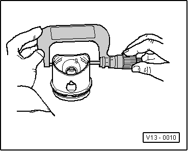
| q | Checking ring gap → Fig.. |
| q | Checking ring-to-groove clearance → Fig.. |
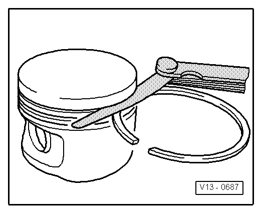
| 5 - | Oil scraper rings |
| q | Carefully remove and install 3-part oil scraper rings by hand. |
| q | Checking ring gap → Fig.. |
| q | Ring-to-groove clearance not measurable. |
| 6 - | Conrod |
| q | Renew as set only. |
| q | Mark with cylinder number -A-. |
| q | Installation position: Marking -B- faces towards pulley end. |
| q | Guided axially by piston. |
| 7 - | Conrod bearing cap |
| q | The caps only fit in one position and only on the appropriate conrod due to the breaking procedure (cracking) separating the cap from the conrod. |
| 8 - | Conrod bolt |
| q | M7×0.75: 20 Nm + 1/4 turn (90°) further. |
| q | M8×1: 30 Nm + 1/4 turn (90°) further. |
| q | Renew. |
| q | Oil threads and contact surface. |
| q | To measure radial clearance, tighten to corresponding specified torque but not further. |
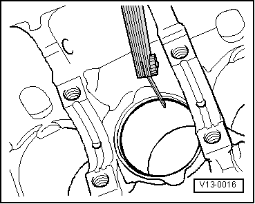
| 9 - | Cylinder block |
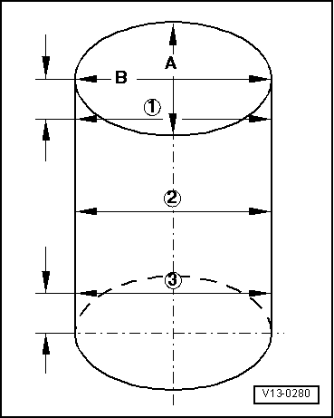
| q | Checking cylinder bores → Fig.. |
| q | Piston and cylinder dimensions → Chapter. |
| 10 - | Bearing shell |
| q | Do not interchange used bearing shells. |
| q | Insert bearing shells centrally. |
| Check radial clearance with Plastigage. |
Note| Do not rotate crankshaft when checking radial clearance. |
| q | New: 0.020…0.061 mm. |
| q | Wear limit: 0.091 mm |
|
|
| Piston ring dimensions in mm | New | Wear limit |
| 1st compression ring | 0.20...0.50 | 1.0 |
| 2nd compression ring | 0.40...0.70 | 1.0 |
| Oil scraper ring | 0.40...1.40 | --- → Remark |
|
|
|
| Piston ring dimensions in mm | New | Wear limit |
| 1st compression ring | 0.04...0.08 | 0.15 |
| 2nd compression ring | 0.04...0.08 | 0.15 |
| Oil scraper ring | Not measurable | |
|
|
Note
|
|