
Golf Mk6
| Repairing subframe |

| Special tools and workshop equipment required |
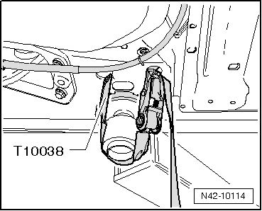
| t | Tensioning strap -T10038- |
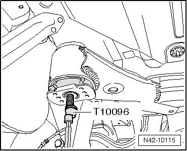
| t | Locating pins -T10096- |
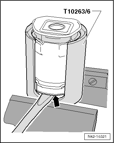
| t | Assembly tool -T10263- |
| t | Engine and gearbox jack -V.A.G 1383 A- |
| t | Hydraulic press -VAS 6178- and thrust piece -T10205/13- |
| t | Foot pump -VAS 6179- |
|
 Note
Note
|
|
|
|
 WARNING
|
|
Note
|
|
Note
|
|
Note
|
|
|
|
|
|
|
|
|
|
Note
|
|
|
|
|
|
Note
|
|
Note
|
|
Note
|
|
|
|
|
|
|
|
|
|
| Specified torques |
| Component | Specified torque | ||
Subframe to body
| 90 Nm + 90° further |