volkswagen Workshop Repair Guides

Volkswagen Workshop Service and Repair Manuals

Removing and installing steering box, right-hand drive vehicle > < Assembly overview - electromechanical steering box, right-hand drive
Removing and installing steering box, left-hand drive vehicle
   
Removing and installing steering box, left-hand drive vehicle
Special tools and workshop equipment required
t  Torque wrench -V.A.G 1331-
t  Torque wrench -V.A.G 1332-
t  Engine and gearbox jack -V.A.G 1383 A-
t  Ball joint puller -3287 A-

Removing steering box
–  Turn steering wheel to straight-ahead position and remove ignition key so that the steering lock engages.
Vehicles with keyless locking and starting system „Keyless Access“
–  Switch off ignition and open driver's door so that the steering lock engages.
Continuation for all vehicles
–  Disconnect battery. → Rep. gr.27
   
–  Remove footwell trim -1-.
  N48-10333
–  Remove bolt -1- and pull universal joint -2- off steering box.
–  Remove front wheels.
–  Loosen nut on track rod ball joint but do not remove completely.
  Caution
Leave nut screwed on a few turns to protect thread on pin.
  N48-10149
–  Press track rod ball joint off wheel bearing housing with -3287A-.
–  Remove lower noise insulation → Rep. gr.50.
  N48-10011
–  Unbolt nuts -1- from left and right coupling rods -2-.
–  Pull out coupling rods -2- from anti-roll bar -3-.
  N40-10319
–  Remove nuts -arrows-.
  N40-10005
–  Disconnect pendulum support from gearbox by removing bolts -14-.
  N40-10341
–  Detach exhaust system bracket from subframe -arrows-.
  N40-10295
–  Remove bolts -arrows- on heat shield, if present.
–  Remove heat shield from subframe, if present.
  N48-10012
–  Remove bolts -5- and -6- for steering box.
  N40-10336
–  Remove bolts -7- and -8- for anti-roll bar.
–  Fix position of subframe and brackets. → Chapter
–  Separate connector for extended service intervals on oil sump.
  N40-10337
–  Position engine and gearbox jack -V.A.G 1383 A- under subframe.
–  Place a wooden block -1- or similar between V.A.G 1383 A and subframe.
  N40-10028
–  Remove bolts -9- and -10- and lower subframe with bracket slightly. Observe electrical wiring.
  N40-10338
–  Remove heat shield -1- over steering box.
–  Remove bolts -arrows-.
  N48-10014
–  Remove cable guide from subframe -arrow-.
–  Unclip all remaining cable clips on steering box.
  N48-10013
–  Pull connectors -arrows- off steering box.
–  Lower subframe carefully with engine/gearbox jack -V.A.G 1383 A-.
  N48-10347
–  Now lift anti-roll bar -1- forwards over subframe -2- and down while turning anti-roll bar slightly.
–  Unbolt steering box from subframe.
  N40-10029
–  Set steering box down as illustrated.
This prevents damage to the control unit -1-.
Installing steering box
Install in reverse order.
Threaded sleeves of steering box must seat in holes in left bracket.
  N48-10332
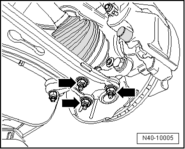
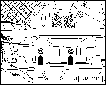
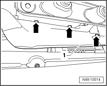
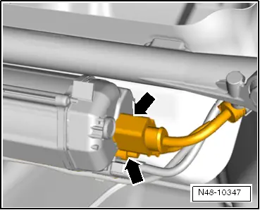
–  Push on connectors -arrows- so that they engage audibly.
  Note
t  
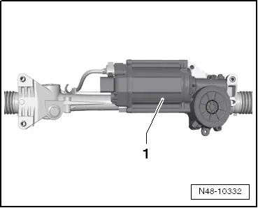
Coat seal on steering box with suitable lubricant, e.g. soft soap, before installing steering box.
t  
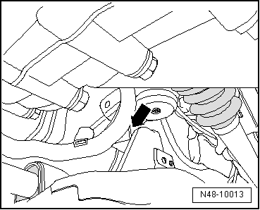
After fitting the steering box to the jointed shaft, ensure that the seal is not kinked when lying against the assembly plate and that the opening to the footwell is correctly sealed. Otherwise, this can result in water leaks and/or noise.
t  
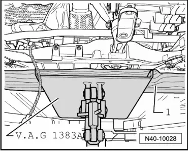
Ensure sealing surfaces are clean.
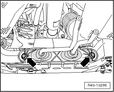
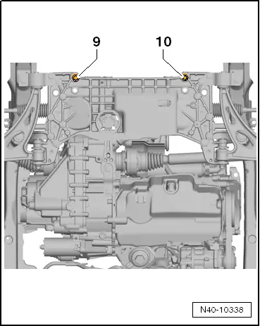
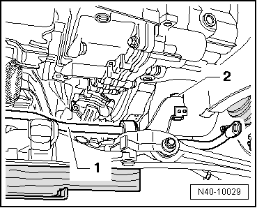
Before inserting subframe bolts, position steering box on subframe and insert bolts for steering box and anti-roll bar.
–  Connect electrical connections to steering box.
–  Install lower noise insulation. → Rep. gr.50.
  Note
Ensure that bellows are not damaged or twisted.
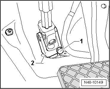
–  Bolt universal joint to steering box.
–  Connect battery. → Rep. gr.27
–  Carry out basic setting for steering angle sender -G85- using vehicle diagnosis, testing and information system -VAS 5051- → Vehicle diagnostic tester.
If new steering box has been installed, adapt electromechanical steering using vehicle diagnostic, testing and information system -VAS 5051-.
–  Carry out adaption of electromechanical steering using vehicle diagnosis, testing and information system -VAS 5051- → Vehicle diagnostic tester.
Running gear
Electromechanical power steering
01 - System capable of self-diagnosis
Electromechanical steering system
Functions
Adapting electromechanical steering
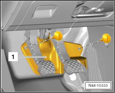
After installation, check position of steering wheel during road test.
If steering wheel is crooked or a new steering box was installed, wheels must be aligned.
–  Check wheel alignment. → Chapter
  N48-10347
Specified torques
ComponentSpecified torque
Subframe to body
t  Use new bolts
70 Nm + 90°
Anti-roll bar to subframe
t  Use new bolts
20 Nm + 90°
Anti-roll bar to coupling rod
t  Use new nut
t  Counterhold on multi-point socket of joint pin
65 Nm
Swivel joint to cast steel suspension link
t  Use new nuts
60 Nm
Swivel joint to sheet steel or forged aluminium suspension link
t  Use new nuts
100 Nm
Shield to subframe
t  Bolt M6 is self-locking
6 Nm
Steering box to subframe
t  Use new bolts
50 Nm + 90°
Universal joint to steering box
t  Use new bolt
30 Nm
Shield to steering box
t  Bolt M6 is self-locking
6 Nm
Track rod ball joint to wheel bearing housing
t  Use new nut
20 Nm + 90°
Exhaust system bracket to subframe
→ Engine; Rep. gr.26

   
Torque specifications for pendulum support to gearbox
BoltSpecified torque
M10 x 35
t  Use new bolt
50 Nm + 90° further
M10 x 75
t  Use new bolt
50 Nm + 90° further


Removing and installing steering box, right-hand drive vehicle > < Assembly overview - electromechanical steering box, right-hand drive