
Golf Mk6
|
 Caution
|
|
|
|
 Note
Note
Note |
|
|

|
|
|
|
|
Note
|
|
|
|
|
|
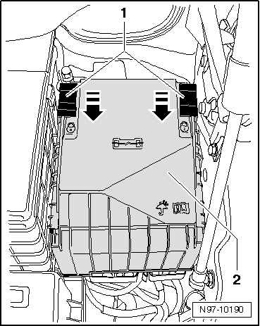
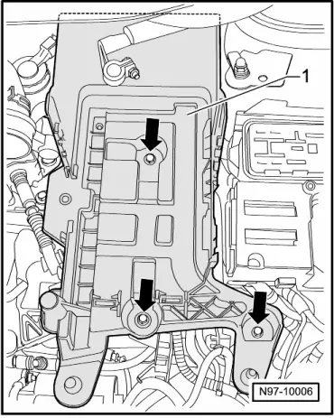
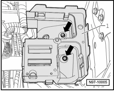
| Threaded connections | Specified torques | |
| Securing nuts -1- | M5 (8 mm) | 4 Nm |
| Securing nuts -1- | M6 (10 mm) | 6 Nm |
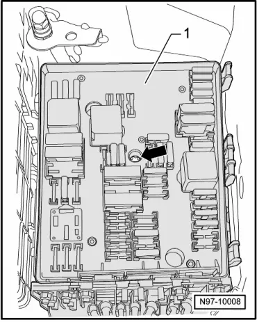
| Electronics box central bolt | 9 Nm |
Note
|
|