
Golf L4-1588cc 1.6L DSL SOHC Turbo (1985)
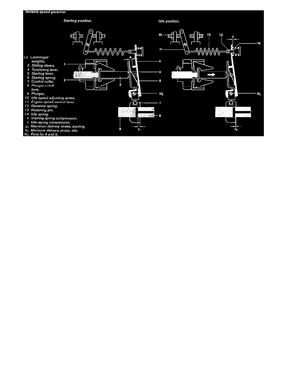
Fig. 8 Variable Speed Governer
Fig. 8 shows the arrangement and functions of a variable-speed governor's components. The input shaft drives the governor assembly, which consists
of a centrifugal-weight housing and the weights themselves as well as the governor spring and lever assembly. This assembly is mounted in the housing
so that it can rotate around the fixed governor axis. Radial motion of the centrifugal weights is translated into axial movement of the sliding sleeve; the
force acting on this sleeve and its position influence the position of the governor mechanism.
In turn, the governor mechanism consists of control lever, tensioning lever and starting lever; the control lever is pivoted in the pump housing and can
be adjusted by the fuel-delivery adjusting screw. The starting and tensioning lever also rotate relative to the control lever.
The starting lever has a ball pin on its underside that engages with the control collar. The starting spring is attached to its upper end. At the upper end
of the tensioning lever is a retaining pin over which is fitted the idle spring. The governor spring is also hooked into the end of the retaining pin. A lever
and the control-lever shaft connect to the engine-speed control lever.
Interaction of spring and sleeve force defines the governor position; control movement is transferred to the control collar, thus determining the
quantity of fuel delivered by the distributor plunger.
Engine Braking
In downhill operation the conditions are reversed. The engine is driven by the vehicle; engine speed tends to increase. The weights swing outward and
the sleeve pushes against the starting and tensioning levers, which in turn move the control collar toward less fuel delivery. This continues until the
smaller delivery corresponds to the new load condition, at the extreme falling to zero. If the engine is completely unloaded, maximum idle speed is
reached.
The processes described here for the variable-speed governor are valid for all positions of the speed-control lever when engine speed or load changes
sufficiently that the control collar moves to either its full-load or stop position.
Governor Functions
Idle-speed regulation -- Ensures that engine speed does not fall below the controlled idle speed.
Maximum no-load speed -- When load is removed, maximum full load speed may not increase to more than the high idle-speed limit. The governor
provides for this by moving the control spool in the "stop" direction; the engine thus receives less fuel.
Intermediate speed control -- There is also intermediate speed control; engine speeds between idle and maximum can thus be controlled within certain
limits.
In addition to these, the governor has other control functions:
Releasing or blocking the extra quantity necessary for starting.
Altering full-load fuel delivery according to engine speed (torque control).
Various add-on modules are required for these functions.
Idle Speed Control