
Golf III L4-1984cc 2.0L SOHC (1993)
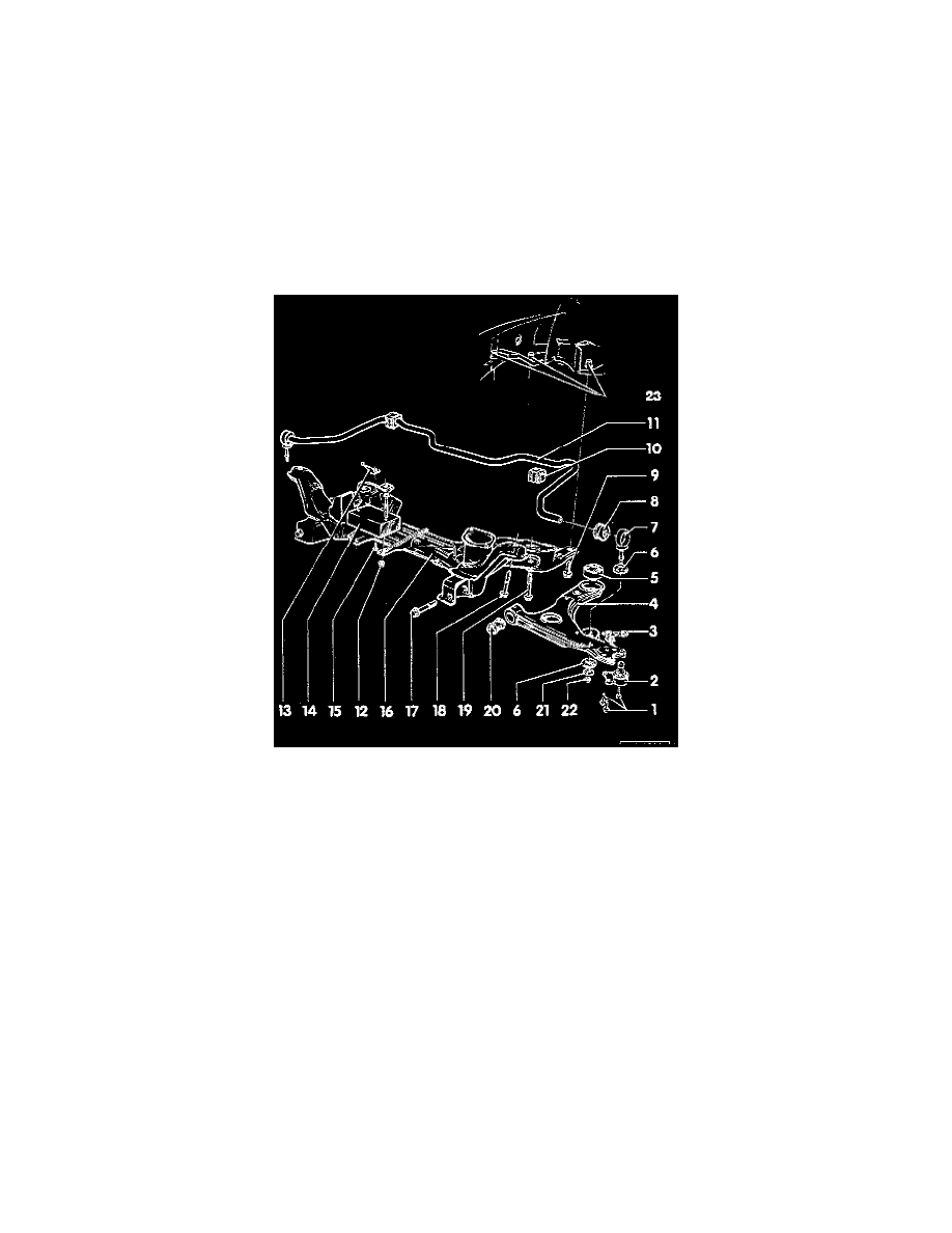
Front Cross-Member: Service and Repair
Replacement
CAUTION:
-
If a vehicle has to be moved after removing the axle shaft, install an outer constant velocity joint and tighten to 50 Nm (37 ft. lbs.) to prevent
damage to wheel bearing.
-
DO NOT attempt to straighten or weld suspension strut, wheel bearing housing, control arm or any other wheel locating or load-bearing
components of the front suspension.
-
Always replace self-locking nuts.
-
Directly below the component legend are the Fig. numbers. Please refer to these for information regarding removal and installation instructions.
NOTE:
-
Always replace corroded bolts/nuts.
-
For this procedure, use the tools shown in the following illustrations or their equivalents.
1
Ball Joint Bolt
-
Tighten to: 35 Nm (26 ft. lbs.)
2
Ball Joint
-
Checking. See: Ball Joint/Testing and Inspection
-
Check rubber boot for damage and replace joint if necessary
-
Mark installation position before removing
-
If replacing, install part centered in elongated hole and check toe setting
-
Elongated holes are NOT intended for camber adjustment
3
Mounting Plate
4
Control Arm
5
Rear Bushing For Control Arm
-
Installation position, refer to Fig. 3
-
Pressing out/in, refer to Fig. 4
-
Modified version available as a replacement. See: Control Arm/Control Arm Bushing/Application and ID
6
Link Rod Bearing
-
Conical Side Faces Control Arm