
Jetta L4-1588cc 1.6L DSL SOHC Turbo (1985)
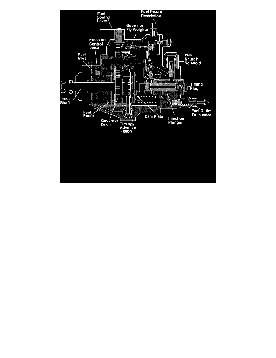
Fig. 2 Diesel Fuel Injection Pump
See Fig. 2 for a cut-away drawing of the fuel pump.
The distributor pump's input shaft runs in bearings in the pump housing and drives the supply pump. Inside the pump at the end of the drive shaft is
located the roller ring. It is not connected to the drive shaft but is held in the pump housing. By way of the cam plate - which rides on the rollers of the
roller ring and is driven by the input shaft - a rotary-reciprocating motion is generated which, in turn, is transferred to the distributor plunger. The
plunger moves inside the distributor head which is bolted to the pump housing. In the distributor head are located the electric fuel shutoff, a screw plug
with vent screw and the pressure valves with their mountings.
A gearset connecting input shaft and governor drives the governor group, which includes centrifugal weights and a sliding sleeve. The governor
mechanism, which consists of control, starting and tensioning levers, rotates in bearings inside the housing and influences the control collar's position on
the plunger. On the governor mechanism's top side is the governor spring, which connects to the control lever by means of the control-lever shaft. In turn,
the control-lever shaft is carried in bearings in the governor cover, whereby the pump function is influenced by the control lever. The governor cover
forms the top of the distributor pump and also contains the full-load adjusting screw, overflow restriction and engine-speed adjusting screw.
The hydraulic injection-timing unit is at the bottom of the distributor pump and at right angles to the pump's longitudinal axis. Its function is
influenced by the pump-cavity pressure, which in turn is determined by the supply pump and pressure-control valve. The advance unit is closed on both
sides by a cover plate.
Pump Drive
The distributor fuel-injection pump is engine-driven; for four-stroke engines it runs at half crankshaft speed, or camshaft speed. It must be positively
driven so that the injection pump's input shaft runs fully synchronously with the engine's piston motion. To avoid confusing the port's order with cylinder
numbers, they are labeled A, B, C, and D.
General Functions
Bosch VE fuel-injection systems have a vane-type fuel-supply pump that draws fuel from the fuel tank and delivers it to the injection-pump cavity.
The supply pump delivers a virtually constant flow of fuel. To obtain a defined pressure level proportional to engine speed, a pressure-control valve is
required. With this valve, pressure can be set to correspond to a particular engine speed. This means that the pump-cavity pressure increases along with
rising engine speed.