volkswagen Workshop Repair Guides

Volkswagen Workshop Service and Repair Manuals

Reworking valve seats > < Removing and installing cylinder head
4-Cyl. fuel injection engine (4-valve), Mechanics
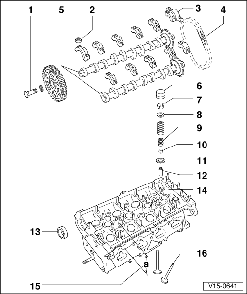
Servicing valve gear
 
V15-0641

Note:

Cylinder heads which have cracks between the valve seats or between valve seat inserts and the spark plug thread can be used further without reducing service life, provided the cracks do not exceed a maximum of 0.5 mm in width, or when no more than the first spark plug thread is cracked.

  • 65 Nm
  • 15 Nm
  • Bearing cap
    • ◆ Installation position => Fig. 2
    • ◆ Installation sequence
      , removing and installing camshaft
    • ◆ Lightly coat bearing cap contact surfaces on camshaft sprocket and on distributor with sealing compound AMV 174 004 01
 
V15-0641
  • Drive chain
    • ◆ Before removing mark D.O.R. (installation position)
      => Page 15-23
  • Camshafts
    • ◆ Checking axial clearance => Fig. 1
    • ◆ Removing and installing
      => Page 15-23
    • ◆ Checking radial clearance with plastigage
           Wear limit: 0.1 mm
    • ◆ Run-out: max. 0.01 mm
    • ◆ Identification and valve timing
      => Page 15-16 , Fig. 3
  • Bucket tappet
    • ◆ Do not interchange
    • ◆ With hydraulic valve clearance compensation
    • ◆ Checking => Page 15-22
    • ◆ Store with cam contact surface downwards
    • ◆ Before installing check camshaft axial clearance => Fig. 1
    • ◆ Oil contact surface
 
V15-0641
  • Cotters
  • Upper valve spring plate
  • Valve springs
    • ◆ Removing and installing:
      Cylinder head
      removed: with 2037
      installed: => Page 15-29 , renewing valve stem seals
  • Valve stem seal
  • Lower valve spring plate
  • Valve guide
    • ◆ Checking => Page 15-27
    • ◆ Renewing => Page 15-27
    • ◆ Service version with collar
  • Oil seal
    • ◆ Lightly oil sealing lip of oil seal
    • ◆ Renewing=> Page 15-20
 
V15-0641
  • Cylinder head
    • ◆ Reworking valve seats
      => Page 15-17
  • Reworking dimension
    • ◆ Measure through a bolt hole
           Min. dimension: 118.1 mm
  • Valves
    • ◆ Do not rework only grinding-in is permitted
    • ◆ Valve dimensions => Fig. 4
 
V15-0456

→ Fig. 1     Checking camshaft axial clearance

Special tools, testers and auxiliary items

  • ◆ Universal dial gauge bracket VW 387
  • ◆ Dial gauge

Check with bucket tappets removed and with first and last bearing caps fitted.

Wear limit: max. 0.15 mm

 
V15-0650

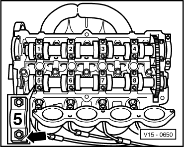
→ Fig. 2     Fitting position of camshaft bearing caps

The recesses on the bearing caps must face towards intake side of cylinder head -arrow-.

 
V15-0846

→ Fig.3     Camshaft identification, valve timing

Identification between pairs of cams cylinder 1 and 2 -arrows-:

     Exhaust shaft -A-: 051 102

     Inlet shaft -B-: 051 101 or 051 101A

Valve timing at 1 mm valve lift

Inlet opens:
Inlet closes:
Exhaust opens:
Exhaust closes:

1 °
38 °
39 °
1 °

before TDC
after BDC
before BDC
after TDC

 
V15-0024

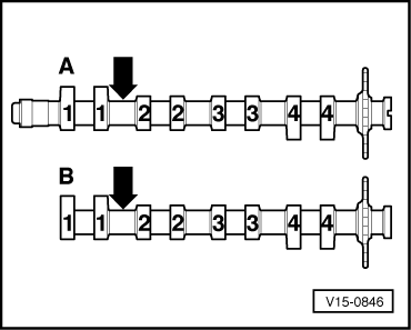
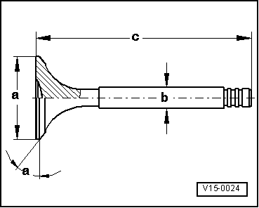
→ Fig. 4     Valve dimensions

Note:

Valves must not be reworked. Only lapping-in is permitted.

Dimension

Inlet valve

Exhaust valve

øa

mm

32,0

27,0

øb

mm

6.97

6.94

c

mm

95,5

98,0

α

45

45

Reworking valve seats > < Removing and installing cylinder head