volkswagen Workshop Repair Guides

Volkswagen Workshop Service and Repair Manuals

Safety precautions when working on the fuel supply system > < Removing and installing parts of fuel supply system
4-Cyl. fuel injection engine (4-valve), Mechanics
Removing and installing parts of fuel supply system
Removing and installing fuel tank with its attachments
 
N20-0015
  • Cap
  • Seal
    • ◆ Renew if damaged
  • Retaining ring
  • Rubber cup
  • Earth connection
  • O ring
    • ◆ Renew if damaged
  • Vent valve
    • ◆ Checking , Fig.2
  • Union nut
 
N20-0015
  • Return hose
    • ◆ Blue or blue markings
    • ◆ From fuel manifold

=> Repair group 24; Digifant injection and ignition system; Servicing injection part

  • Union nut
    • ◆ Remove and install with 3218
  • Flange
    • ◆ Note fitting position on fuel tank , Fig. 1
  • Supply hose
  • Sealing ring
    • ◆ Coat with petrol when installing
    • ◆ Renew if damaged
  • Return hose
 
N20-0015
  • Fuel gauge sender
  • Fuel delivery unit
    • ◆ Removing and installing
      => Page 20-10
    • ◆ Checking fuel pump
      => Page 20-12
  • Securing strap
    • ◆ Note differing length
  • Bracket
    • ◆ For securing straps
  • 25 Nm
  • Fuel tank
    • ◆ Support with engine and gearbox jack V.A.G 1383 A when removing
 
N20-0015
  • Supply pipe
    • ◆ Black
    • ◆ To fuel manifold

=> Repair group 24; Digifant injection and ignition system; Servicing injection part

  • Fuel filter
    • ◆ Installation position: Arrow points in through-flow direction or marking AUSLAUF and OUT to front
  • Retaining clip
  • Vent hose
    • ◆ Fuel tank vent shown: Saloon
    • ◆ Fuel tank venting for Variant
      => Page 20-8 , Fig. 3
  • Reservoir
    • ◆ Type shown: Saloon
    • ◆ Type for Variant
      => Page 20-8 , Fig. 3
 
N20-0015
  • 10 Nm
  • Breather pipe
    • ◆ To activated charcoal filter , Pos. 6
  • Gravity valve
    • ◆ To remove valve unclip upwards out of filler neck
    • ◆ Check valve for through-flow
      valve vertical: open,
      valve tilted 45 °: closed
 
V20-1041

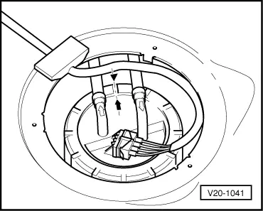
→ Fig. 1     Fitting position of fuel delivery unit flange

Marking on the flange must align with marking on the fuel tank.

 
N20-0016

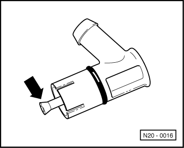
→ Fig. 2     Checking breather valve

Lever in rest position: Closed

Lever pushed in direction of arrow: Open

 
V20-1135

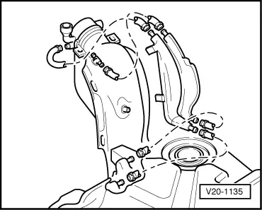
→ Fig. 3     Fuel tank venting Variant

Safety precautions when working on the fuel supply system > < Removing and installing parts of fuel supply system