volkswagen Workshop Repair Guides

Volkswagen Workshop Service and Repair Manuals

Piston and cylinder dimensions > < Crankshaft dimensions
4-cyl. fuel injection engine (cross-flow cylinder head)
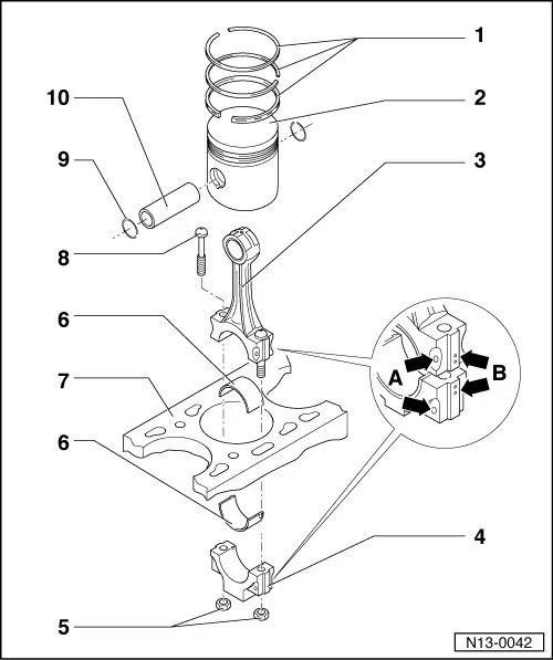
Dismantling and assembling pistons and conrods
 
N13-0042
  • Piston ring
    • ◆ Offset gaps by 120 °
    • ◆ Remove and install with piston ring pliers
    • ◆ "TOP" faces towards piston crown
    • ◆ Checking ring gap=> Fig. 1
    • ◆ Checking ring to groove clearance
      => Fig. 2
  • Piston
    • ◆ Checking => Fig. 3
    • ◆ Mark installation position and cylinder number
    • ◆ Arrow on piston crown points to pulley end
    • ◆ Install using piston ring clamp
    • ◆ Characteristics=> Fig. 4
 
N13-0042
  • Conrod
    • ◆ Only renew as a set
    • ◆ Mark cylinder number -B-
    • ◆ Installation position:
      Marking -A- faces towards pulley end
    • ◆ With oil drilling for piston pin lubrication
  • Conrod bearing cap
    • ◆ Note installation position
  • 30 Nm + 1/4 turn (90 °) further
    • ◆ Oil threads and contact surface
    • ◆ To measure radial clearance tighten to 30 Nm but not further
 
N13-0042
  • Bearing shell
    • ◆ Note installation position
    • ◆ Do not interchange used bearing shells
    • ◆ Ensure retaining lugs fit tightly in recesses
    • ◆ Axial clearance
      New: 0.05...0.31 mm
      Wear limit: 0.37 mm
    • ◆ Check radial clearance with Plastigage:
      New: 0.01...0.06 mm
      Wear limit: 0.12 mm
      Do not rotate crankshaft when checking radial clearance
    • ◆ With oil drilling for piston pin lubrication
 
N13-0042
  • Cylinder block
    • ◆ Checking cylinder bores
      =>Fig. 5
    • ◆ Piston and cylinder dimensions
      =>Page 13-41
  • Conrod bolt
  • Circlip
  • Piston pin
    • ◆ If difficult to remove, heat piston to 60 °C
    • ◆ Remove and install with VW 222a

Special tools, testers and auxiliary items

  • ◆ Feeler gauges
  • ◆ Internal dial gauge 50...100 mm
  • ◆ Micrometer 75...100 mm
 
V13-0016

→ Fig. 1     Checking piston ring gap

  • ‒ Push ring squarely from above down to approx. 15 mm from bottom end of cylinder.

Piston ring

Gap

New

Wear
limit

Compression rings

mm

0.20...0.40

1.0

Oil scraper ring

mm

0.25...0.50

1.0

 
V13-0687

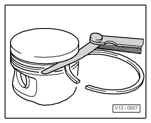
→ Fig. 2     Checking ring to groove clearance

Clean groove before check.

Piston ring

Clearance

New

Wear
limit

Compression rings

mm

0.02...0.05

0.15

Oil scraper ring

mm

0.02...0.05

0.15

 
V13-0010

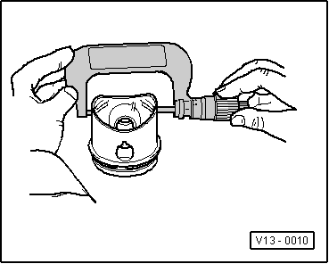
→ Fig. 3     Checking piston

Measure pistons approx. 10 mm from the lower edge of skirt, at 90 ° to the piston pin axis.

Deviation from nominal dimension
     max. 0.04 mm

 
V13-1229

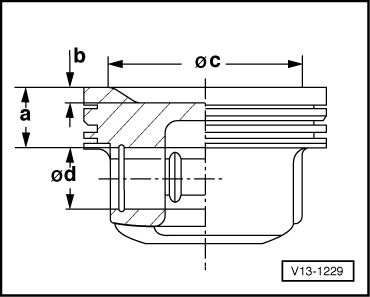
→ Fig. 4     Piston characteristics

Engine codes

AEK, AFT

Dimension "a"

mm

22.0

Dimension "b"

mm

2.3

Recess ø "c"

mm

61.4

Piston pin ø "d"

mm

20.0

When repairing an engine only pistons and piston rings of the same type and pistons with the same weight class may be installed.

 
V13-0280

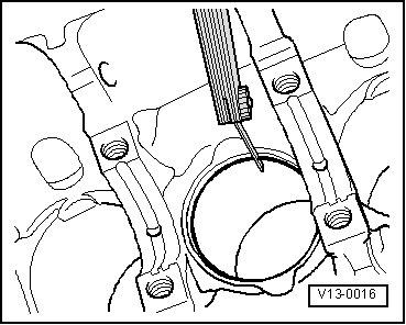
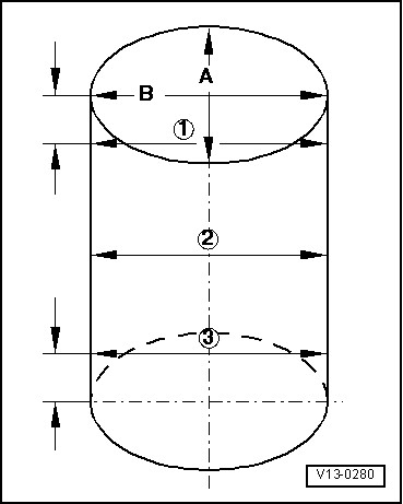
→ Fig. 5     Checking cylinder bores

  • ◆ Use internal dial gauge 50...100 mm.
  • ◆ Measure bores at 3 locations in both directions -A- across the engine and -B- in line with crankshaft.
  • ◆ Deviation from nominal dimension
         max. 0.08 mm

Note:

Measuring the cylinder bores must not be done when the cylinder block is mounted on a repair stand with adapter bracket VW 540, as incorrect measurements would then be possible.

Piston and cylinder dimensions > < Crankshaft dimensions