
Passat (B3)
|
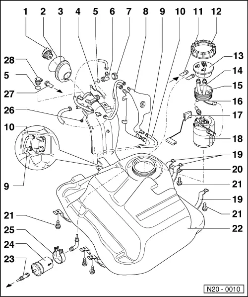
Removing and installing parts of fuel supply system
Removing and installing fuel tank with its attachments and fuel filter
|
 |
|
|
Note: After all repairs to the fuel supply unit or the fuel gauge sender unit have been carried out, ensure the the supply or return flow hoses do not make contact with the fuel tank (pump noises may be transferred).
|
|
|
=> Repair group 24; mixture preparation, injection
|
|
|
|
|
|
|
|
 |
|
|
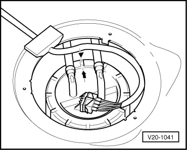
→ Fig. 1 Installation position of fuel delivery unit flange Marking on the flange must align with marking on the fuel tank. |
 |
|
|
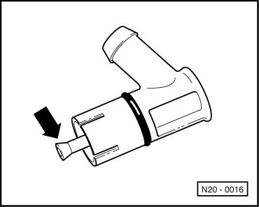
→ Fig. 2 Checking vent valve Lever in rest position: Closed Lever pushed in direction of arrow: Open |