volkswagen Workshop Repair Guides

Volkswagen Workshop Service and Repair Manuals

Notes on installing > < Removing and installing engine
6-cyl. fuel injection engine Mechanics
Removing and installing engine
Notes on removing
  • ‒ The engine is removed forwards together with the gearbox.
  • ‒ With ignition switched off disconnect battery earth strap.

Note:

If necessary the anti-theft coding for the radio must be obtained first.

  • ‒ All cable ties which are opened or cut open when removing engine, must be replaced in the same position when installing engine.
  • ‒ Remove ribbed belt .
 
N10-0017
  • ‒ Remove intake hose:

=> Repair group 24; Motronic injection and ignition system; Servicing injection part

  • ‒ Remove spark plug connectors with ignition cables:

=> Repair group 28; Motronic injection and ignition system; Servicing injection part
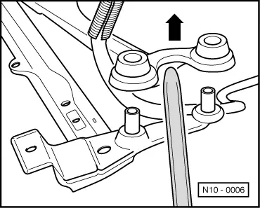
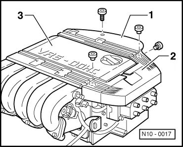
  • ‒ → Remove ignition cable guides -1- and -2-.
  • ‒ Remove cover for intake manifold upper part -3-.
  • ‒ Disconnect accelerator cable at throttle valve housing and support bracket (do not remove locating clip at support bracket).
  • ‒ Loosen P.A.S. reservoir hose clamp.
  • ‒ Unbolt P.A.S. hydraulic pipe retainers from engine carrier and gearbox.
  • ‒ Remove power assisted steering vane pump and lay to side; hoses remain connected.

=> Running gear; Repair group 48; Assembly overview: vane pump, hydraulic pipes, reservoir; Removing and installing P.A.S. vane pump

  • ‒ Removing lock carrier with attachments:

=> General body repairs; Repair group 50; Lock carrier

  • ‒ Drain coolant => Page 19-14
  • ‒ Separate 42-pin connector (near ignition transformer).
  • ‒ Disconnect all electric wires from gearbox, alternator and starter and move clear.
  • ‒ Disconnect all coolant, vacuum and breather hoses from engine.
  • ‒ Disconnect fuel supply and return pipe from fuel manifold and unclip from retainers on cylinder head cover.

Note:

For protection against fuel spray cover connections with a cloth.

  • ‒ Separate 4-pin connector to Lambda probe and 2-pin connector to knock sensor 1 on rear right assembly mounting.
  • ‒ Unbolt drive shafts and tie up.
  • ‒ Remove balance weight and front exhaust pipe from exhaust manifold => Page 26-2 , exhaust manifold, front exhaust pipe and catalyst with attachments.
  • ‒ Pull off vacuum hose between intake manifold upper part and fuel pressure regulator.
  • ‒ Remove intake manifold pressure sender from intake manifold upper part.
  • ‒ Remove radiator with fan and air ducting , parts of cooling system body side.

Vehicles with air conditioner

  • ‒ Observe additional information and removal instructions => Page 10-17 .

Vehicles with manual gearbox

  • ‒ Remove hydraulic clutch slave cylinder:

=> 5-Speed manual gearbox 02A; Repair group 30; Servicing clutch control

  • ‒ Remove gearbox operating cables with support bracket from gearbox:

=> 5-Speed manual gearbox 02A; Repair group 34; Servicing selector mechanism; Removing and installing gear selector cables

 
V10-1114
  • ‒ → Attach lifting tackle 2024 A as follows and lift slightly with workshop crane:
  • Vibration damper end:
    4th hole in hook at position 1
  • Flywheel end:
    4th hole in hook at position 6
Warning!
The hooks and locating pins must be secured with locking pins.

Notes:

  • ◆ The positions marked 1...4 on the bar must be towards the vibration damper.
  • ◆ The holes in the hook rails are counted up from the hook.

Vehicles with automatic gearbox

  • ‒ Remove selector lever cable from gearbox:

=> Automatic gearbox 096; Repair group 37; Servicing selector mechanism; Dismantling and assembling selector mechanism

 
N10-0018
  • ‒ → Attach lifting tackle 2024A with extension 2024 A/1 as follows and lift slightly with workshop crane:
  • Vibration damper end:
    1st hole in extension at position 1
  • Flywheel end:
    3rd hole in extension at position 6
Warning!
The hooks and locating pins must be secured with locking pins.

Notes:

  • ◆ The positions marked 1...4 on the bar must be towards the vibration damper end.
  • ◆ The holes in the hook rails are counted up from the hook.

Continuation for all vehicles

  • ‒ Release gearbox from rear left assembly mounting and engine from rear right assembly mounting.
 
V10-1221
  • ‒ → Release engine at front assembly mounting.
 
N10-0006
  • ‒ → Disconnect engine carrier and on one side lever out distance bracket from rubber mounting.
  • ‒ Take out P.A.S. hydraulic pipes from disconnected engine carrier.
  • ‒ Lever out assembly forwards.

Note:

When the assembly is lifted off, it must be carefully guided to prevent damage to the bodywork.

When working on the engine, it should be secured to the engine stand using the engine bracket 3269.

Notes on installing > < Removing and installing engine