volkswagen Workshop Repair Guides

Volkswagen Workshop Service and Repair Manuals

Reworking valve seats > < Checking compressions
6-cyl. fuel injection engine Mechanics
Servicing valve gear
 
W15-0009

Special tools, workshop equipment, test and measuring appliances and auxiliary items required

  • ◆ 3268 Camshaft bar
  • ◆ VW 387 Universal dial gauge bracket
  • ◆ V.A.G 1331 Torque wrench (5...50 Nm)
  • ◆ V.A.G 1332 Torque wrench (40...200 Nm)
  • ◆ Universal dial gauge
  • ◆ AMV 188 001 02
  • ◆ AMV 174 004 01
 
N15-0006

Note:

Cylinder heads which have cracks between the valve seats or between valve seat inserts and the spark plug thread can be used further without reducing service life, provided the cracks do not exceed a maximum of 0.5 mm in width.

  • Bearing cap
    • ◆ Installation position => Fig. 2
    • ◆ Installation sequence
      => Page15-24 , removing and installing camshafts
  • 20 Nm
 
N15-0006
  • Camshafts
    • ◆ Checking axial clearance => Fig. 1
    • ◆ Removing and installing
    • ◆ Checking radial clearance with plastigage
           Wear limit: 0.1 mm
    • ◆ Run-out: max. 0.01 mm
  • Camshaft sprocket
    • ◆ Removing and installing
      => Page 15-24 , Removing and installing camshafts
  • Sender wheel
    • ◆ For Hall sender (G40)
    • ◆ When installing contact surface on timing chain and sender wheel must be dry
    • ◆ Removing and installing
      => Page 15-24 , removing and installing camshafts
 
N15-0006
  • 100 Nm
    • ◆ To remove and install counter-hold with 24 mm OJ spanner on camshaft
      , removing and installing camshafts
    • ◆ Oil bulkhead contact surface when installing
  • Cylinder head height
    • ◆ Minimum height: a = 139.5 mm
  • Cylinder head
    • ◆ See note
      => Page 15-14
    • ◆ Reworking valve seats
      => Page 15-21
  • Valves
    • ◆ Do not rework only grinding-in is permitted
    • ◆ Valve dimensions => Fig. 3
 
N15-0006
  • Valve guide
    • ◆ Checking => Page 15-30
    • ◆ Renewing => Page 15-31
    • ◆ Service version with collar
  • Valve stem seal
  • Valve springs
    • ◆ Removing and installing:
      Cylinder head
      removed: with 2037
      installed: => Page 15-33 , Renewing valve stem seals
  • Valve spring plate
  • Valve cotters
 
N15-0006
  • Bucket tappet
    • ◆ Do not interchange
    • ◆ With hydraulic valve clearance compensation
    • ◆ Checking => Page 15-28
    • ◆ Store with cam lobe contact surface downwards
    • ◆ Before installing check camshaft axial clearance => Fig. 1
    • ◆ Oil contact surface
 
N15-0011

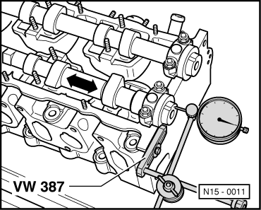
→ Fig. 1     Camshafts, checking axial clearance

Wear limit: max. 0.15 mm

Check with bucket tappets removed and with first and last bearing caps fitted to appropriate camshaft.

 
N15-0007

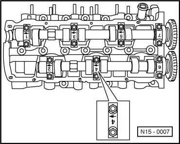
→ Fig. 2     Fitting position of camshaft bearing caps

The bearing cap identification must be readable from the exhaust side of the cylinder had and the arrow pointing to vibration damper end.

 
V15-0024

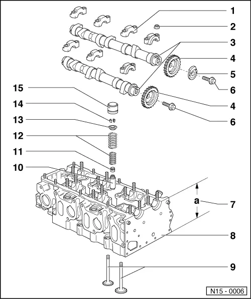
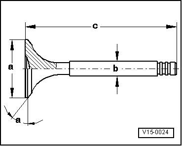
→ Fig. 3     Valve dimensions

Note:

Valves must not be reworked. Only lapping-in is permitted.

Dimension

Inlet valve

Exhaust valve

øa

mm

39.0

34.20

øb

mm

6.97

6.95

c

mm

105.95

106.95

α

45

45

Reworking valve seats > < Checking compressions