
Passat (B3)
 |
|
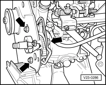
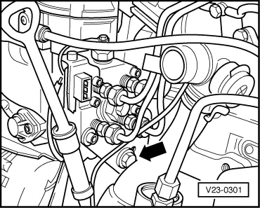
Note: Use open ring spanner 3035 to remove high pressure fuel pipes.
|
 |
|
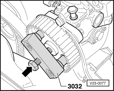
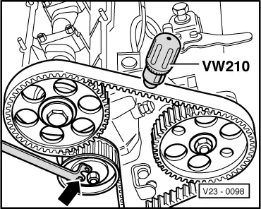
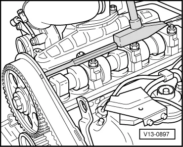
Note: On no account should the bolts holding the injection pump head be loosened. Loosening these bolts allows the head to cant and caurses the distributor plungers to fracture. |
 |
|
|
 |
|
|
 |
|
|
Injection pumps with two-part injection pump sprocket
|
 |
|
Note: |
 |
|
|
Use open ring spanner 3035 to remove high pressure fuel pipes.
|
 |
|
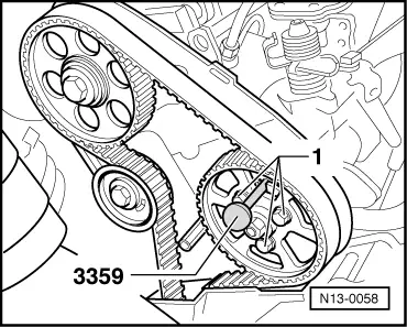
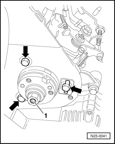
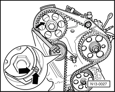
Attention!
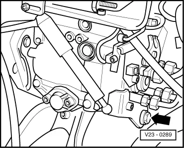
On no account must the injection pump hub nut -1- be loosened. Otherwise the injection pump basic setting will be upset, and it cannot be adjusted with normal workshop equipment. |
 |
|
Installing |
 |
|
|
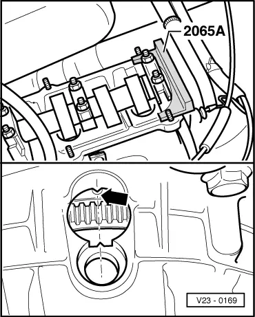
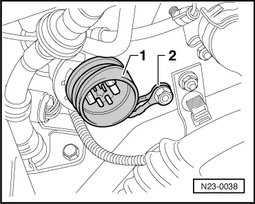
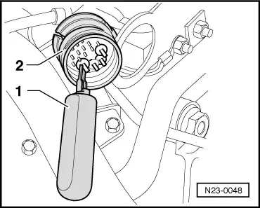
→ If the injection pump is replaced, the spade contacts must be pushed out of the multi-pin connector with the spade terminal release tool.
Injections pumps supplied as a replacement part, are not fitted with a multi-pin connector. The spade connectors on the wires must be located in the multi-pin connector in accordance with the current flow diagram: => Current flow diagrams, Electrical fault finding and Fitting locations binder |
|
|
|
 |
|
|
 |
|
|
|
|
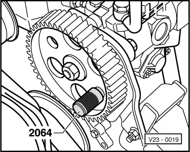
If the injection pump sprocket cannot be locked:
Note: Do not interchange fuel supply and return pipe banjo bolts the return pipe banjo bolt has a smaller internal diameter and "OUT" is marked on the hexagon head.
|