volkswagen Workshop Repair Guides

Volkswagen Workshop Service and Repair Manuals

Checking control unit voltage supply > < Checking engine speed sender
Digifant injection and ignition system (4-valve)
Digifant injection and ignition system
Checking and adjusting idling switch

Checking function

Special tools, testers and auxiliary items

  • ◆ Fault reader V.A.G 1551 with cable V.A.G 1551/3
  • ◆ Test box V.A.G 1598/18
  • ◆ Hand multimeter V.A.G 1526 or multimeter V.A.G 1715
  • ◆ Adapter set V.A.G 1594
  • ◆ Current flow diagram

Test sequence

  • ‒ Connect fault reader V.A.G 1551 and select engine electronics control unit (address word 01); carry out selection with engine idling.
 
→ Indicated on display:
Rapid data transfer     HELP
Select function XX
  • ‒ Input 08 for "Read measured value block" function and confirm with Q.
 
→ Indicated on display:
Read measured value block     HELP
Input display group number XX
  • ‒ Input 01 for "Display group number" and confirm with Q.
 
→ Indicated on display:
(1...4 = Display zones)
Read measured value block     1     ⇒
     1     2     3     4

Note:

If something different is indicated on the display:

=> Fault reader operating instructions

  • ‒ Observe 4th position from left in display zone 4 -8 digit number block-.
         Specification: 0
  • ‒ Open throttle valve slightly. The display at position 4 must jump to 1
         Display: 00010100

If the specifications are not attained:

Display

Cause

Continuation of check

Always 0

Short to earth

=> Page 24-54

Always 1

Open circuit or short to positive

=> Page 24-55

Continuation of check when display = always 0:

 
N24-0104
  • ‒ → Pull 2 pin connector -1- off idling switch (F60) -2-.

Display 1:

  • ‒ Replace idling switch -2.

Display 0:

  • ‒ Press ⇒ key.
  • ‒ Input 06 for "End output" and confirm with Q.
  • ‒ Switch off ignition
  • ‒ Pull connector off Digifant control unit.
  • ‒ Check wiring to control unit at 2 pin connector contact 1 for short to wire contact 2 and to vehicle earth.

If no fault in wire is detected:

  • ‒ Renew Digifant control unit (J169)
    , item 11 .

Continuation of check when display = always 1:

 
N24-0105
  • ‒ → Pull 2 pin connector -1- off idling switch (F60) -2-.
  • ‒ Bridge connector contacts with aux. cables from V.A.G 1594 and observe display.

Display 0:

  • ‒ Replace idling switch -2.

Display 1:

  • ‒ Press ⇒ key.
  • ‒ Input 06 for "End output" and confirm with Q.
 
N24-0094
  • ‒ Switch off ignition
  • ‒ → Connect test box V.A.G 1598/18 to control unit wiring loom.
  • ‒ Check wiring between test box and 2 pin connector for open circuit according to current flow diagram.
         Contact 1+socket 21
         Contact 2+socket 33
         Wire resistance: Max. 1.5 ω

If no wiring fault is detected:

  • ‒ Renew Digifant control unit (J169)
    , item 11 .

Renewing idling switch

Special tools, testers and auxiliary items

  • ◆ Vernier caliper or depth gauge

Work sequence

  • ‒ Remove throttle valve housing.
 
V24-1010
  • ‒ → Measure and note dimension throttle valve to sealing surface -a-.
  • ‒ Renew idling switch (F60) -1-.
  • ‒ Adjust throttle valve by moving the idling switch -1- so that the dimension -a- is set again.

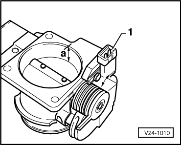
Note:

Setting the throttle valve must be carried out very carefully. On no account must the dimension -a- be exceeded.

Adjusting idling switch

Special tools, testers and auxiliary items

  • ◆ Vernier caliper or depth gauge

Work sequence

 
V24-1010
  • ‒ → Loosen idling switch -1- .
  • ‒ Slowly close throttle valve (the stop on the cam must not touch the idling switch).
  • ‒ Measure and note distance from throttle valve to sealing surface -a-.
  • ‒ Adjust throttle valve by moving the idling switch -1-.
         Adjusting dimension a = noted dimension a + 0.5 mm

Note:

The throttle valve adjustment must be carried out very carefully. On no account must the adjusting dimension -a- be exceeded.

Checking control unit voltage supply > < Checking engine speed sender