volkswagen Workshop Repair Guides

Volkswagen Workshop Service and Repair Manuals

Checking idling stabilization > < Performing basic setting
Digifant injection and ignition system (4-valve)
Digifant injection and ignition system
Checking Lambda probe and Lambda control

Special tools, testers and auxiliary items

  • ◆ Fault reader V.A.G 1551 with cable V.A.G 1551/3
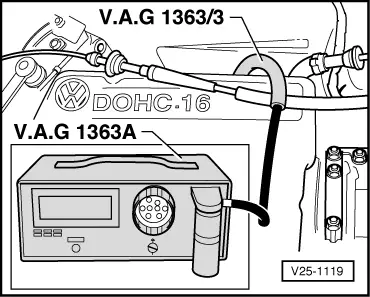
  • ◆ CO tester V.A.G 1363 A or 4 gas tester V.A.G 1788
  • ◆ Adapter V.A.G 1363/3
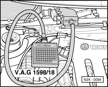
  • ◆ Test box V.A.G 1598/18
  • ◆ Hand multimeter V.A.G 1526 or multimeter V.A.G 1715
  • ◆ Adapter set V.A.G 1594
  • ◆ Current flow diagram

Check conditions

  • ● Idling adjustment OK.
  • ● Exhaust system between catalyst and cylinder head free of leaks

Test sequence

  • ‒ Connect fault reader V.A.G 1551 and select engine electronics control unit (address word 01); carry out selection with engine idling.
 
→ Indicated on display:
Rapid data transfer     HELP
Select function XX
  • ‒ Input 08 for "Read measured value block" function and confirm with Q.
 
→ Indicated on display:
Read measured value block     HELP
Input display group number XX
  • ‒ Input 01 for "Display group number" and confirm with Q.
 
→ Indicated on display:
(1...4 = Display zones)
Read measured value block     1     ⇒
     1     2     3     4

Note:

If something different is indicated on the display:

=> Fault reader operating instructions

Only continue with the test when

 
V25-1119
  • ● The coolant temperature is above 80 °C
    -Display zone 2-
  • ● The engine has then run for a further 2 minutes at idling speed
  • ‒ → Connect CO tester with adapter V.A.G 1363/3 to CO sampling pipe.
  • ‒ Check CO content.
         Specification: 0.3...1.2 Vol.%
  • ‒ Read off Lambda probe voltage in display zone 3. Voltage must fluctuate in the range
         0... 1.0 V
 
N24-0098
  • ‒ → Pull 2 pin connector -1- off coolant temperature sender (G62) -2- . The probe voltage must
         increase
    and then drop back to the old control range.
  • ‒ Reconnect connector. The probe voltage must
         drop back
    and then increase to the old control range.

Note:

The engine speed must not exceed 1500 rpm during the check, otherwise the connector disconnected from the control unit will be recognised as a fault.

  • ‒ Press ⇒ key.
 
N24-0094
  • ‒ Input 06 for "End output" and confirm with Q.
  • ‒ Switch off ignition

If the specifications are not attained:

  • ‒ Check Lambda probe heating => Page 24-62 .
  • ‒ → Connect test box V.A.G 1598/18 to control unit wiring loom.
 
N24-0095
  • ‒ → Separate 4 pin connector to Lambda probe -1-.
  • ‒ Check wiring between test box and 4 pin connector for open circuit according to current flow diagram.
         Contact 3+socket 42
         Contact 1+socket 20
         Wire resistance: Max. 1.5 ω
  • ‒ Check wiring at 4 pin connector for short to one another.
         Specification: ∞ω
  • ‒ Check screening -test box socket 65- for short to the probe wiring according to current flow diagram.
         Specification: ∞ω

If the specifications are not attained:

  • ‒ Renew Lambda probe (G39).

Checking idling stabilization > < Performing basic setting