volkswagen Workshop Repair Guides

Volkswagen Workshop Service and Repair Manuals

Checking signal from automatic gearbox > < Checking speed signal
Motronic fuel injection and ignition system 08.95 ä
Motronic injection and ignition system
Checking control unit voltage supply

Special tools, testers and auxiliary items

  • ◆ Fault reader V.A.G 1551 or vehicle system tester V.A.G 1552 with cable V.A.G 1551/3
  • ◆ Test box V.A.G 1598/18
  • ◆ Hand multimeter V.A.G 1526 or multimeter V.A.G 1715
  • ◆ Adapter set V.A.G 1594
  • ◆ Current flow diagram

Test sequence

  • ‒ Connect fault reader V.A.G 1551 (V.A.G 1552) and select engine electronics control unit with the "Address word" 01. When doing this the ignition must be switched on.
    (Connecting fault reader and selecting engine electronics control unit .)
 
→ Indicated on display:
Rapid data transfer     HELP
Select function XX
  • ‒ Press keys 0 and 8 for the function "Read measured value block" and confirm entry with Q key.
 
→ Indicated on display:
Read measured value block     HELP
Input display group number XXX
  • ‒ Press keys 0, 0 and 2 for "Display group number 2" and confirm entry with Q key.
 
→ Indicated on display:
(1...4 = Display zones)
Read measured value block 2     ⇒
     1     2     3     4
  • ‒ Check the battery voltage (display zone 3).

Display zones

1

2

3

4

Display group 2: General engine data

Display

xxxx rpm

xx.xx ms

xx.xxx

x.x

Indicated

Engine speed

Injection period

Battery voltage

Tank breather adaption value

Working range

800...6000 rpm

0.00...25.00 ms

0.000...16.500 V

---

Specific.

0 rpm

---

12.000...14.500 V

---

---

---

If specification is not attained , evaluating display group 2

---

  • ‒ Press ⇒key.
  • ‒ Press keys 0 and 6 for the "End data transfer" function and confirm input with the Q key.

Evaluating display group 2

Display group: 2

Display zone: 3

Possible fault cause

Fault elimination

If no display appears on V.A.G 1551

Fuse 15 defective

- Replace fuse

Wiring open circuit

- Check voltage supply terminal 15 => Page 24-112

If the figure displayed fluctuates between 12.0...14.5 V

Loose contact

- Check voltage supply terminal 30 => Page 24-111

0.0...12.0 V

Battery discharged/defective
Voltage regulator defective

- Check battery
Check alternator
Check voltage regulator

14.5...16.5 V

Alternator defective
Voltage regulator defective

- Check alternator
Check voltage regulator

Checking voltage supply terminal 30

  • ‒ Switch off ignition.
 
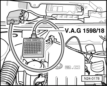
N24-0178
  • ‒ → Connect test box V.A.G 1598/18 to control unit wiring loom -arrow-.
  • ‒ Connect multimeter using aux. cables from V.A.G 1594 to measure voltage at sockets 1+54:
         Specification: 12...14.5 V

If the specification is not obtained:

  • ‒ Check wiring according to current flow diagram.

Checking voltage supply terminal 15

 
N24-0178
  • ‒ Switch off ignition.
  • ‒ → Connect test box V.A.G 1598/18 to control unit wiring loom -arrow-.
  • ‒ Switch ignition on.
  • ‒ Connect multimeter using aux. cables from V.A.G 1594 to measure voltage at sockets 1+23:
         Specification: 12...14.5 V

If the specification is not obtained:

  • ‒ Check wiring according to current flow diagram.

Checking signal from automatic gearbox > < Checking speed signal