volkswagen Workshop Repair Guides

Volkswagen Workshop Service and Repair Manuals

Checking intake manifold temperature sender > < Performing basic setting
Motronic fuel injection and ignition system 08.95 ä
Motronic injection and ignition system
Checking coolant temperature sender

Special tools, testers and auxiliary items

  • ◆ Fault reader V.A.G 1551 or vehicle system tester V.A.G 1552 with cable V.A.G 1551/3
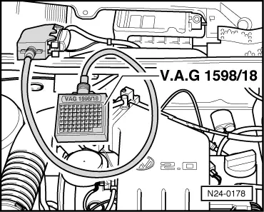
  • ◆ Test box V.A.G 1598/18
  • ◆ Hand multimeter V.A.G 1526 or multimeter V.A.G 1715
  • ◆ Adapter set V.A.G 1594
  • ◆ Current flow diagram

Note:

If an engine is brought to operating temperature with the vehicle stationary, and due to unfavourable conditions the time taken to reach operating temperature is too long, it can lead to fault code P0116 or P0125 being stored in fault memory. In this case it is advisable to erase fault memory and bring engine to operating temperature during a test drive.

Test conditions

  • ● Engine cold

Test sequence

  • ‒ Connect fault reader V.A.G 1551 (V.A.G 1552) and select engine electronics control unit with the "Address word" 01. When doing this the ignition must be switched on.
    (Connecting fault reader and selecting engine electronics control unit .)
 
→ Indicated on display:
Rapid data transfer     HELP
Select function XX
  • ‒ Press keys 0 and 8 for the function "Read measured value block" and confirm entry with Q key.
 
→ Indicated on display:
Read measured value block     HELP
Input display group number XXX
  • ‒ Press keys 0, 0 and 1 for "Display group number 1" and confirm entry with Q key.
 
→ Indicated on display:
(1...4 = Display zones)
Read measured value block 1     ⇒
     1     2     3     4
  • ‒ Check the specification for coolant temperaturesender (display zone 2):

Display zones

1

2

3

4

Display group 1: Idling test

Display

xxxx rpm

xxx.x °C

xx.x%

xx.x <°

Indicated

Engine speed

Coolant temperature

Lambda control

Ignition angle

Working range

800...6000 rpm

-46.5...141.0 °C

-25.0...25.0 %

0.0...50.0 <°

Specification

0 rpm

Approx. ambient temperature1)

The value must fluctuate at least 3 % in range -5.0...5.0 %

2.0...15.0 <°

---

If specification is not attained ,
evaluating display group 1

---

---

1)     If a temperature is displayed which deviates greatly from the ambient temperature of the sender, check sender wiring for transfer resistances/open circuit.

Continuation:

  • ‒ Start engine and run at idling speed.
    The temperature value must
         increase uniformly

If the specification is not obtained:

  • ‒ Replace coolant temperature sender (G62).
  • ‒ Press ⇒key.
  • ‒ Press keys 0 and 6 for the "End data transfer" function and confirm input with the Q key.
  • ‒ Switch off ignition.

Notes:

  • ◆ Display on fault reader jumps by 1.5 °C
  • ◆ If irregular engine running occurs in certain temperature ranges and the temperature figure does not increase without interruption, the temperature signal is temporarily interrupted and the sender must be renewed.

Evaluating display group 1

Display group: 1

Display zone: 2

Possible fault cause

Fault elimination

Approx. -46.6 °C

Wiring open circuit or short to positive

- Check wiring => Page 24-94

Approx. 141.0 °C

Short to earth

Checking wiring

 
N24-0178
  • ‒ → Connect test box V.A.G 1598/18 to control unit wiring loom -arrow-.
 
N24-0167
  • ‒ → Pull 4 pin connector -1- off coolant temperature sender (G62) -2-.
 
N24-0172
  • ‒ → Check wiring between test box and 4 pin connector for open circuit according to current flow diagram.
         Contact 1+socket 33
         Contact 3+socket 14
         Wire resistance: Max. 1.5 ω
  • ‒ Check wire between control unit connector and 4 pin connector contact 3 for short to wire contact 1 and to vehicle earth, according to current flow diagram.
         Contact 3+socket 33
         Contact 3+vehicle earth
         Specification: ∞ω
  • ‒ Additionally check both wires for short to battery positive.
         Specification: ∞ω

If no fault in wire is detected:

  • ‒ Perform resistance measurement at coolant temperature sender (G62) contacts 1+3, resistance figures => Page 24-20 , Fig. 1

If the specification is not obtained:

  • ‒ Replace coolant temperature sender (G62).
  • ‒ Read-out the readiness code=> Page 01-34 .

Checking intake manifold temperature sender > < Performing basic setting