-
‒ →
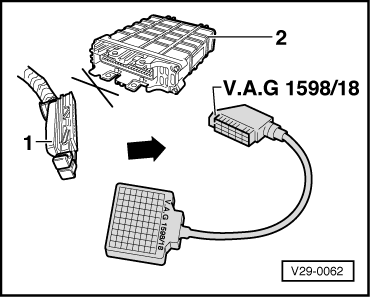
With ignition switched off pull connector -1- off Motronic control unit (J220).
-
‒ Connect test box to wiring loom connector.
-
‒ Carry out check according to following table
.
Attention!
To prevent damage to the electronic components, switch to the respective measuring range before connecting the measuring cable, observe the test conditions and carry out the additional work listed in the table.
Note:
After completing the electrical check, on vehicles with automatic gearbox, the fault "Engine/gearbox electrical connection: open circuit"caused by the check and stored in the automatic gearbox control unit must be erased.
=> Automatic gearbox 096; Repair Group 01; Self-diagnosis; erasing fault memory
Test table
|
- Measuring range: Switch to voltage measurement -V-.
|
|
Test step
|
Item checked
|
▪ Test conditions
- additional work
|
Test box sockets
|
Specifications1)
|
|
1
|
Motronic control unit (J220) fault memory voltage supply
|
▪ Ignition switched off
|
1 + 54
|
Approx. battery voltage
|
|
2
|
Motronic control unit (J220) fault memory voltage supply via current supply relay (J271)
|
▪ Ignition switched off
Bridge sockets 9 + 55 on test box
|
1 + 23
|
Approx. battery voltage
|
|
|
|
- Switch ignition on
|
1 + 38
|
|
|
3
|
Wiring to fuel pump relay (J17)
|
- Ignition switched on
|
Bridge
6 + 55
|
Fuel pump must be heard to run
|
|
4
|
Air mass meter (G70) voltage supply via current supply relay (J271)
|
▪ Ignition switched on
Pull connector off air mass meter and connect multimeter to connector contacts 1 + 32)
|
Bridge
9 + 55
|
Approx. battery voltage
|
1)
Observe notes
2)
Connector pin assignment => Page 01-55, Fig. 7
|
▪ Measuring range: Voltage measurement -V- selected
|
|
Test step
|
Item checked
|
▪ Test conditions
- additional work
|
Test box sockets
|
Specifications1)
|
|
5
|
Lambda probe heating relay (J278)
|
▪ Ignition switched on
Separate connector to Lambda probe and connect multimeter to connector contacts 1 + 22)
Bridge test box sockets 56 + 6
Bridge test box sockets 9 + 55
|
Bridge
1 + 28
|
Approx. battery voltage
|
|
6
|
Speedometer sender (G22)
|
▪ Ignition switched on
▪ Selector lever in position "D"3)
Lift front left wheel and turn
|
56 + 65
|
Fluctuates between 0...at least 4 V
|
1)
Observe notes => Page 01-40
2)
Connector pin assignment => Page 01-53
, Fig. 3
3)
Only for vehicles with automatic gearbox
|
▪ Measuring range: Voltage measurement -V- selected
|
|
Test step
|
Item checked
|
▪ Test conditions
- additional work
|
Test box sockets
|
Specifications1)
|
|
7
|
Earth wire 72)
|
---
|
7 + 54
|
Approx. battery voltage
|
|
Only vehicles with automatic gearbox: Test step 8, 9 and 10
|
|
8
|
Earth wire 58 to code control unit (J220)
|
---
|
54 + 58
|
Approx. battery voltage
|
|
9
|
Earth wire 7
|
▪ Selector lever in position "P" or "N"
|
7 + 54
|
Approx. battery voltage
|
|
|
|
▪ Selector lever in position "D, 1, 2, 3" or "R"
|
|
Approx. 0 V
|
|
10
|
Wiring to starter inhibitor and reverse light relay (J226)
|
▪ Selector lever in position "P"
Pull (3 pin) connector off ignition transformer
Operate starter
|
1 + 7
|
Approx. 2 V below battery voltage
|
1)
Observe notes => Page 01-40
2)
Only for vehicles with manual gearbox
|
▪ Measuring range: Voltage measurement -V- selected
|
|
Test step
|
Item checked
|
▪ Test conditions
- additional work
|
Test box sockets
|
Specifications1)
|
|
Only vehicles with air conditioning: Test step 11 and 12
|
|
11
|
Wiring from air conditioner (not on Climatronic)
|
▪ Ignition switched on
Switch air conditioner on
|
39 + 55
|
Approx. battery voltage
|
|
12
|
Wiring to air conditioner compressor
|
▪ Ignition switched on
|
Briefly
bridge
37 + 38
|
Air conditioner compressor magnetic coupling must be heard to switch
|
1)
Observe notes => Page 01-40
|
- Switch off ignition.
Measuring range: Switch to resistance measurement-ω- .
|
|
Test step
|
Item checked
|
▪ Test conditions
- additional work
|
Test box sockets
|
Specifications1)
|
|
13
|
Wiring with injector Cyl. 1 (N30)
|
---
|
23 + 24
|
14...21.5 ω
|
|
14
|
Wiring with injector Cyl. 2 (N31)
|
---
|
2 + 23
|
14...21.5 ω
|
|
15
|
Wiring with injector Cyl. 3 (N32)
|
---
|
23 + 25
|
14...21.5 ω
|
|
16
|
Wiring with injector Cyl. 4 (N33)
|
---
|
23 + 26
|
14...21.5 ω
|
|
17
|
Wiring with activated charcoal filter solenoid valve 1 (N80)
|
---
|
23 + 31
|
40...80 ω
|
|
182)
|
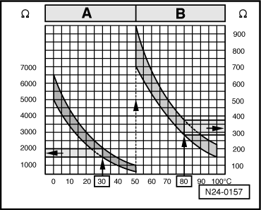
Wiring with coolant temperature sender (G62)
|
---
|
14 + 33
|
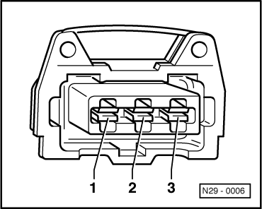
=> Page 01-52
, Fig. 1
|
1)
Observe notes => Page 01-40
2)
If the self diagnosis indicates a sender fault which is not established by this test, it could be caused by a temporary break in the temperature signal. In this case, additionally check the coolant temperature sender => Page 24-40
.
|
▪ Ignition switched off
▪ Measuring range: Resistance measurement-ω- selected
|
|
Test step
|
Item checked
|
▪ Test conditions
- additional work
|
Test box sockets
|
Specifications1)
|
|
19
|
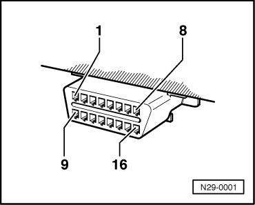
Wiring to diagnostic socket (16 pin)
|
---
|
43 +
Contact 72) on diagnostic socket
|
Max. 1.5 ω
|
|
20
|
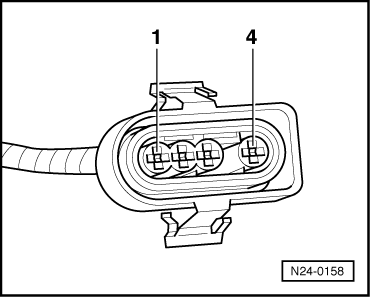
Wiring to Lambda probe
(G39)
|
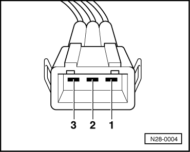
- Disconnect connector to Lambda probe
Bridge contacts 3 + 4 of connector3)
|
20 + 42
|
max. 1.5 ω
|
|
|
|
- Reconnect connectors
|
|
∞ω
|
1)
Observe notes => Page 01-40
2)
Connector pin assignment => Page 01-52
, Fig. 2
3)
Connector pin assignment => Page 01-53
, Fig. 3
|
▪ Ignition switched off
▪ Measuring range: Resistance measurement-ω- selected
|
|
Test step
|
Item checked
|
▪ Test conditions
- additional work
|
Test box sockets
|
Specifications1)
|
|
21
|
Wiring with throttle valve potentiometer (G69)
|
---
|
33 + 41
|
1.60...2.40 kω
|
|
|
|
▪ Throttle valve closed
|
33 + 40
|
1.00...2.00 kω
|
|
|
|
▪ Throttle valve closed
|
40 + 41
|
2.50...3.50 kω
|
|
|
|
▪ Throttle valve closed
|
40 + 41
|
2.50...4.00 kω
|
|
|
|
- Open throttle valve
|
|
Resistance must decrease
|
|
22
|
Wiring to Hall sender
(G40)
|
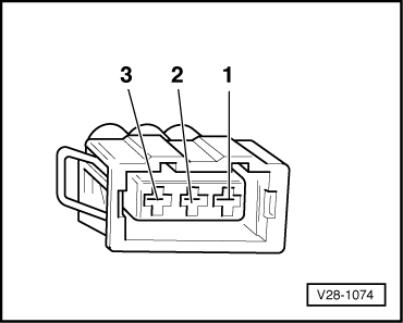
- Pull connector off Hall sender (G40)
Bridge connector contacts 1 + 32)
|
41 + 56
|
max. 1.5 ω
|
|
|
|
- Bridge connector contacts 1 + 22)
|
44 + 56
|
|
1)
Observe notes => Page 01-40
2)
Connector pin assignment => Page 01-53
, Fig. 4
|
▪ Ignition switched off
▪ Measuring range: Resistance measurement-ω- selected
|
|
Test step
|
Item checked
|
▪ Test conditions
- additional work
|
Test box sockets
|
Specifications1)
|
|
23
|
Wiring to ignition transformer output stage (N152)
|
- Pull connector off output stage
|
8 + 55
38 + 55
|
∞ω
|
|
|
|
- Bridge connector contacts 1 + 22)
|
8 + 55
|
max. 1.5 ω
|
|
|
|
- Bridge connector contacts 1 + 32)
|
38 + 55
|
max. 1.5 ω
|
|
24
|
Wiring to knock sensor 1 (G61)
|
---
|
33 + 34
34 + 56
|
∞ω
|
|
|
3 pin connector (blue) before distributor
|
- Separate connector to knock sensor
Bridge connector contacts 1 + 23)
|
33 + 34
|
max. 1.5 ω
|
|
|
|
- Bridge connector contacts 1 + 33)
|
34 + 56
|
max. 1.5 ω
|
|
25
|
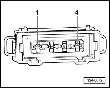
Wiring with intake manifold temperature sender (G72)
|
---
|
33 + 36
|
=> Page 01-52
, Fig. 1
|
1)
Observe notes => Page 01-40
2)
Connector pin assignment => Page 01-54
, Fig. 5
3)
Connector pin assignment => Page 01-54
, Fig. 6
|
▪ Ignition switched off
▪ Measuring range: Resistance measurement-ω- selected
|
|
Test step
|
Item checked
|
▪ Test conditions
- additional work
|
Test box sockets
|
Specifications1)
|
|
26
|
Wiring with idling speed stabilization valve (N71)
|
---
|
27 + 53
|
7...10 ω
|
|
|
|
- Pull connector off valve
|
|
∞ω
|
|
27
|
Wiring to air mass meter (G70)
|
- Pull connector off air mass meter
Bridge connector contacts 1 + 22)
|
1 + 16
|
max. 1.5 ω
|
|
|
|
- Bridge connector contacts 1 + 32)
|
1 + 23
|
|
|
|
|
- Bridge connector contacts 1 + 42)
|
1 + 17
|
|
|
28
|
Wiring with engine speed sender (G28)
|
---
|
67 + 68
|
500...700 ω
|
|
|
3 pin connector (white) before distributor
|
|
56 + 67
56 + 68
|
∞ω
|
1)
Observe notes => Page 01-40
2)
Connector pin assignment => Page 01-55, Fig. 7
|