volkswagen Workshop Repair Guides

Volkswagen Workshop Service and Repair Manuals

Checking knock sensors > < Checking Hall sender
Motronic injection and ignition system (6-Cyl. engine)
Servicing ignition
Checking ignition transformer

Special tools, testers, measuring instruments and auxiliary items required

  • ◆ Test box V.A.G 1598/18
  • ◆ Hand multimeter V.A.G 1526 or multimeter V.A.G 1715
  • ◆ Diode test lamp V.A.G 1527
  • ◆ Adapter set V.A.G 1594
  • ◆ Current flow diagram

Check conditions

  • ● Fault is recognised by self diagnosis
  • ● Battery voltage at least 11.5 V
  • ● Engine speed sender OK, checking
  • ● Hall sender OK, checking

Test sequence

 
N10-0017
  • ‒ → Pull ignition cables off ignition transformer and remove ignition cable duct -2-.

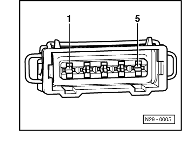
Checking voltage supply

 
N28-0029
  • ‒ → Pull 5 pin connector off ignition transformer -arrow-
 
N29-0005
  • ‒ → Check voltage between contacts 1+5 of detached connector.
  • ‒ Switch on ignition.
         Specification: Min. 11.5 V
  • ‒ Switch off ignition.

If no voltage is present:
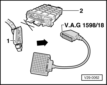
  • ‒ Check wire between 5 pin connector contact 1 and earth for open circuit according to current flow diagram.
         Wire resistance: Max. 1.5 ω
  • ‒ Check wire between 5 pin connector contact 5 and relay plate for open circuit according to current flow diagram.
         Wire resistance: Max. 1.5 ω
 
N29-0005

Checking activation

  • ‒ Remove fuse 18.
  • ‒ → Connect diode test lamp V.A.G 1527 using aux. cables from V.A.G 1594 to disconnected connector contacts
         5 and 2 (ignition output 1).
  • ‒ Operate starter and check ignition signal from Motronic control unit.
         LED must flicker.
  • ‒ Repeat test at contacts
         5 and 3 (ignition output 3),
         5 and 4 (ignition output 2).
 
V29-0062
  • ‒ Switch off ignition

The LED flickers:

  • ‒ Replace ignition transformer (N152)
    , item 6 .

The LED does not flicker:

  • ‒ → Connect test box V.A.G 1598/18 to control unit wiring loom.
 
N29-0005
  • ‒ → Check wiring between test box and 5 pin connector for open circuit according to current flow diagram.
         Contact 2+socket 8
         Contact 3+socket 50
         Contact 4+socket 52
         Wire resistance: Max. 1.5 ω
 
N29-0005
  • ‒ → Check wiring at 5 pin connector for short to one another.
         Contact 2+socket 60
         Contact 2+socket 52
         Contact 3+socket 52
         Specification: ∞ω

If no wiring fault is detected and voltage was present between contacts 1+5:

  • ‒ Renew engine electronics control unit .

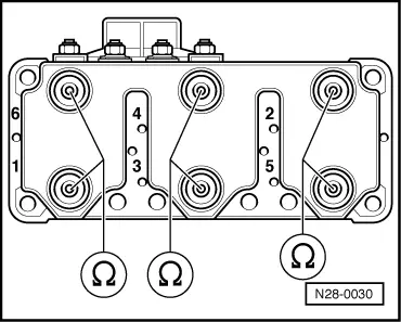
Checking secondary winding

 
N28-0030
  • ‒ → Check secondary winding at terminal 4 between
         Cyl. 1 and Cyl. 6,
         Cyl. 3 and Cyl. 4,
         Cyl. 2 and Cyl. 5.
    Specification: 3.6... 4.4 kω

If the specifications are not attained:

  • ‒ Replace ignition transformer (N152)
    , item 6 .

Checking knock sensors > < Checking Hall sender