Checking Knock Sensors on Passat (B3) 6-Cyl Engine
 |
|
|
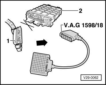
Test sequence
|
 |
|
|
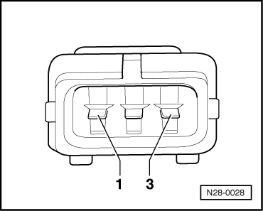
Knock sensor 1 (G61)
|
 |
|
|
Knock sensor 2 (G66)
|
 |
|
|
 |
|
If no wiring fault is detected:
If the fault is still present (fault again in fault memory):
|

|
|
|
Test sequence
|
|
|
|
Knock sensor 1 (G61)
|
|
|
|
Knock sensor 2 (G66)
|
|
|
|
|
|
If no wiring fault is detected:
If the fault is still present (fault again in fault memory):
|