volkswagen Workshop Repair Guides

Volkswagen Workshop Service and Repair Manuals

Checking Lambda probe heating > < Performing basic setting
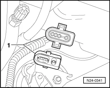
Simos injection and ignition system
Checking Lambda probe and Lambda control

Special tools, testers and auxiliary items

  • ◆ Fault reader V.A.G 1551 or vehicle system tester V.A.G 1552 with cable V.A.G 1551/3
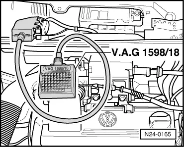
  • ◆ Test box V.A.G 1598/18
  • ◆ Hand multimeter V.A.G 1526 or multimeter V.A.G 1715
  • ◆ Adapter set V.A.G 1594
  • ◆ Current flow diagram

Check conditions

  • ● Coolant temperature at least 80 °C
  • ● Exhaust system between catalyst and cylinder head free of leaks

Functional check

  • ‒ Connect fault reader V.A.G 1551 (V.A.G 1552) and select engine electronics control unit with the "Address word" 01. When doing this the engine must be running at idling speed.
    (Connecting fault reader and selecting engine electronics control unit .)
 
→ Indicated on display:
Rapid data transfer     HELP
Select function XX
  • ‒ Press keys 0 and 8 for the function "Read measured value block" and confirm entry with Q key.
 
→ Indicated on display:
Read measured value block     HELP
Input display group number XX
  • ‒ Press keys 0 and 5 for "Display group number 05" and confirm entry with Q key.
 
→ Indicated on display:
(1...4 = Display zones)
Read measured value block     5     ⇒
     1     2     3     4
  • ‒ Checking Lambda control operating condition in display zone 4:

Lambda control operating condition display:

  • ◆ Lambda control on stop:
  • 5th position from right must display 0
         Display:: 00000000
  • ◆ Lambda control active:
  • 4th position from right must display 1
         Display: 00001000
  • ◆ Fault in fault memory:
  • 3rd position from right must display 0
         Display:: 00000000
  • ◆ Lambda probe operationally ready:
  • 2nd position from right must display 1
         Display: 00000010
  • ◆ Mixture:
  • 1st position from right must display 0 and 1 alternately
         Display: 00000001 (1 = rich mixture)
         Display: 00000000 (0 = lean mixture)
  • ‒ Press C key.
  • ‒ Press keys 0 and 1 for "Display group number 01" and confirm entry with Q key.
 
→ Indicated on display:
(1...4 = Display zones)
Read measured value block     1     ⇒
     1     2     3     4
  • ‒ Observe Lambda probe voltage in display zone 3. The voltage must fluctuate
         at least 30 time per minute
    in the range
         ADY, AGG: 0...1.1 V
         AFT: 0.2... 1.0 V.

Display

Cause

Continuation of check

approx. 2.51 V

Short to positive

=> Page 24-43 Checking basic voltage

approx. 1.50... 1.60 V

Open circuit

=> Page 24-44 , checking wiring

approx. 0.50 V

Short to wire 2

approx. 0.15... 0.20 V

Short to earth

fluctuates between 0...1.1 V or
0.2... 1.0 V

Control OK.

---

  • ‒ Press ⇒key.
  • ‒ Press keys 0 and 6 for the function "End output" and confirm entry with the Q key.

If the specifications for Lambda control operating conditions are not attained or the probe voltage does not fluctuate as stated:

  • ‒ Check Lambda probe heating => Page 24-46 .
  • ‒ Check Lambda probe for soot. Renew if necessary.

Checking basic voltage

 
N24-0341
  • ‒ → Separate 4 pin connector (black) to Lambda probe before catalyst (G39) -1-.
 
N24-0342
  • ‒ → Connect multimeter with aux. cables from V.A.G 1594 to measure voltage at contacts 3+4 (connector to engine control unit).
  • ‒ Switch on ignition and measure basic voltage.
         Specification: 1.30...1.40 V
  • ‒ Switch off ignition.

If the specification is not obtained:

  • ‒ Check Lambda probe wiring
    => Page 24-44

If the specification is attained:

  • ‒ Replace Lambda probe (G39).

Checking Lambda probe wiring

 
N24-0165
  • ‒ → Connect test box V.A.G 1598/18 to control unit wiring loom.
 
N24-0341
  • ‒ → Separate 4 pin connector (black) to Lambda probe before catalyst (G39) -1-.
 
N24-0165
  • ‒ → Check wiring between test box and 4 pin connector for open circuit according to current flow diagram.
         Contact 3+socket 42
         Contact 4+socket 17
         Wire resistance: Max. 1.5 ω
  • ‒ Check wiring at 4 pin connector for short to one another.
         Contact 1+socket 20
         Contact 1+socket 42
         Contact 1+socket 17
         Contact 2+socket 17
         Contact 2+socket 42
         Contact 3+socket 17
         Specification: ∞ω
  • ‒ Check screening wire -test box socket 21- for short to the probe wiring according to current flow diagram.
         Contact 1+socket 21
         Contact 2+socket 21
         Contact 3+socket 21
         Contact 4+socket 21
         Specification: ∞ω
  • ‒ Additionally check all wiring for short to battery positive and to vehicle earth.

If a fault in wire is detected:

  • ‒ Check wiring according to current flow diagram.

If no wiring fault is detected:

  • ‒ Replace Lambda probe (G39).
<SOURCEMARKET> </SOURCEMARKET> <SOURCESYSTEM> </SOURCESYSTEM>

Checking Lambda probe heating > < Performing basic setting