volkswagen Workshop Repair Guides

Volkswagen Workshop Service and Repair Manuals

Read measured value block > < Fault table
Simos injection and ignition system
Self diagnosis
Final control diagnosis

The final control diagnosis activates the following components in the stated sequence:

1.

Fuel pump relay (J17)

2.

Activated charcoal filter solenoid valve 1 (N80)

Engine codes ADY and AGG

3.

Exhaust gas recirculation valve (N18), (two-way valve)1)

     1)     Ignore display

Engine code AFT

3.

Intake manifold change-over valve (N156), (two-way valve)

Special tools, testers and auxiliary items

  • ◆ Fault reader V.A.G 1551 with cable V.A.G 1551/3
  • ◆ Test box V.A.G 1598/18
  • ◆ Adapter set V.A.G 1594
  • ◆ Diode test lamp V.A.G 1527
  • ◆ Current flow diagram

Test conditions

  • ● Fuse 15,18 and 22 OK.

Work sequence

  • ‒ Connect fault reader V.A.G 1551 (V.A.G 1552) and select engine electronics control unit with the "Address word" 01. When doing this the ignition must be switched on.
    (Connecting fault reader and selecting engine electronics control unit .)
 
→ Indicated on display:
Rapid data transfer     HELP
Select function XX
  • ‒ Operate fault reader taking into account the information on the display:
  • ‒ Press keys 0 and 3 for the function "Final control diagnosis".
 
→ Indicated on display:
Rapid data transfer     Q
03 Final control diagnosis

Activating fuel pump relay (J17):

  • ‒ Confirm input with Q key.
 
→ Indicated on display:
Final control diagnosis     ⇒
Fuel pump relay J17
  • The fuel pump relay (on the relay plate with fuse box, relay position 12) must click until switching to the next final control by pressing the ⇒button.

Note:

During the activation of the fuel pump relay the fuel pump must be heard to run at intervals.

If the relay does not click:

  • ‒ Check fuel pump relay:

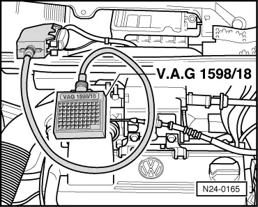
=> Current flow diagrams, Electrical fault finding and Fitting locations, Fuel supply system.

Activating activated charcoal filter solenoid valve 1 (N80):

Test conditions

  • ● Fuse 15 OK.
  • ‒ Press ⇒key.
 
→ Indicated on display:
Final control diagnosis     ⇒
Solenoid valve 1 for activated charcoal filter N80
  • The activated charcoal filter solenoid valve 1 (on air cleaner housing) must click until the next final control element is selected by pressing the ⇒ button.

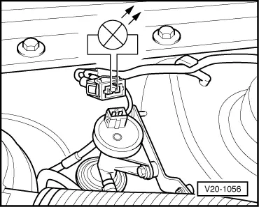
The valve clicks but a fault is still suspected (valve does not open or close):

  • ‒ Remove air cleaner
  • ‒ Pull hose off solenoid valve (from activated charcoal filter).
  • ‒ Connect auxiliary hose.
  • ‒ During final control diagnosis blow into auxiliary hose (in direction of throttle housing).
         Valve must open and close

If the solenoid valve does not click:

 
V20-1056
  • ‒ → Pull 2 pin connector off valve and connect diode test lamp V.A.G 1527 with aux. cables from V.A.G 1594 to disconnected connector.
         The LED must flash

LED flashes:

  • ‒ Renew solenoid valve.

LED does not flash:

  • ‒ Switch off ignition.
 
N24-0165
  • ‒ → Connect test box V.A.G 1598/18 to control unit wiring loom -arrow-.
  • ‒ Check wire between test box socket 33+2 pin connector contact 1 for open circuit according to current flow diagram.
         Wire resistance: Max. 1.5 ω

If no fault in wire is detected:

  • ‒ Check solenoid valve voltage supply according to current flow diagram, if necessary renew Simos control unit (J361).

Engine codes ADY and AGG

  • ‒ Press ⇒key.
 
→ Indicated on display:
Final control diagnosis     ⇒
Exhaust gas recirculation valve -N18
  • ‒ Press ⇒key.

Engine code AFT

Activate intake manifold change-over valve (N156):

  • ‒ Press ⇒key.
 
→ Indicated on display:
Final control diagnosis     ⇒
Intake manifold change-over valve -N156
 
N24-0348
  • ‒ → Pull 2 pin connector -1- off valve -2- and connect diode test lamp V.A.G 1527 with aux. cables from V.A.G 1594 to disconnected connector.
         The LED must flash

LED does not flash:

  • ‒ Switch off ignition.
 
N24-0165
  • ‒ → Connect test box V.A.G 1598/18 to control unit wiring loom -arrow-.
  • ‒ Check wire between test box socket 22 and 2 pin connector contact 2 for open circuit according to current flow diagram.
         Wire resistance: Max. 1.5 ω

If no fault in wire is detected:

  • ‒ Check intake manifold change-over valve (N156) voltage supply according to current flow diagram. 2 pin connector contact 1 and vehicle earth.
         Specification: min. 11 V

If the voltage supply is OK and no fault is present in the wiring:

  • ‒ Check intake manifold change-over valve => Page 24-52 .

Continued for all engine codes

  • ‒ Press ⇒key.

Note:

After completion of the final control diagnosis input 06 for "End output" function and confirm with Q.

  • ‒ Switch off ignition.
<SOURCEMARKET> </SOURCEMARKET> <SOURCESYSTEM> </SOURCESYSTEM>

Read measured value block > < Fault table