-
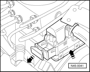
‒ →
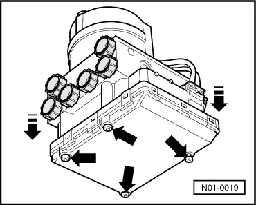
Remove bolts from control unit and pull control unit off.
Do not cant control unit when pulling off.
Cover control unit solenoids with a lint-free cloth.
After separating control unit/hydraulic unit use transportation protection for valve dome.
=>Booklet Running gear, Technical Bulletin No. 6
Installing:
Notes:
-
◆ Only remove sealing plugs on hydraulic unit when the relevant brake pipe is going to be fitted.
-
◆ If the sealing plugs are removed too early, brake fluid can escape, it can then no longer be guaranteed that the unit is sufficiently filled or adequately bled.
-
◆ There must be nothing in the area of the control unit that can contaminate the valve block.
-
‒ Bolt control unit to hydraulic unit. Observe tightening torque, max. 4 Nm. (Always use screws supplied).
-
‒ Connect hydraulic pump motor connector.
-
‒ Further installation is carried out in the reverse sequence
-
‒ Bleeding brake system =>Booklet Running gear; Repair group 47
-
‒ Coding control unit =>Page 01-113
|
|
|---|
|
Tightening torques:
|
|
|
For left-hand drive vehicles:
|
|
|
Control unit to hydraulic unit
|
max.
4 Nm
|
|
Torx socket head bolts for hydraulic unit to bracket
|
8 Nm
|
|
Tandem master brake cylinder nut to brake servo
|
25 Nm
|
|
Brake pipes to ABS unit:
|
|
|
Thread M 10 x 1
|
15 Nm
|
|
Thread M 12 x 1
|
15 Nm
|
|
For right-hand drive vehicles:
|
|
|
Control unit to hydraulic unit
|
max.
4 Nm
|
|
Hydraulic unit nut to bracket
|
10 Nm
|
|
Bracket to mounting plate
|
25 Nm
|
|
Brake pipes to ABS unit:
|
|
|
Thread M 10 x 1
|
15 Nm
|
|
Thread M 12 x 1
|
15 Nm
|
|