volkswagen Workshop Repair Guides

Volkswagen Workshop Service and Repair Manuals

Reworking valve seats > < Removing, installing and tensioning toothed belt
3-cyl. diesel engine, Mechanics
Servicing valve gear
 
N15-0327

Notes:

  • ◆ Cylinder heads with cracks between valve seats may be further used without reducing engine life if the cracks are small, maximum 0.5 mm wide.
  • ◆ All bearing and running surfaces must be oiled before assembling.
  • 20 Nm + 1/4 turn (90 °) further
    • ◆ Renew
    • ◆ Note sequence when loosening and tightening
      , Removing and installing camshaft
  • Injector rocker arm shaft
 
N15-0327
  • Cylinder head bolt
    • ◆ Renew
    • ◆ Note sequence when loosening and tightening
      => Page 15-21, removing and installing cylinder head
    • ◆ Before installing, set washers -item 4- in cylinder head
  • Washer
    • ◆ For cylinder head bolts
  • Bucket tappet
    • ◆ Do not interchange
    • ◆ With hydraulic valve clearance compensation
    • ◆ Store with cam lobe contact surface downwards
    • ◆ Before installing check camshaft axial clearance => Fig. 1
    • ◆ Oil contact surface
    • ◆ Before removing, remove camshaft bearing caps
 
N15-0327
  • Cotters
  • Upper valve spring plate
  • Valve spring
    • ◆ Removing and installing:
      Cylinder head
      removed: with 2037
      installed: => Page 15-44, renewing valve stem seals
  • Inner valve spring
    • ◆ Removing and installing:
      Cylinder head
      removed: with 2037
      installed: => Page 15-44, renewing valve stem seals
    • ◆ Set in cylinder head before fitting bearing caps
  • Valve stem seal
    • ◆ Renewing=> Page 15-44
 
N15-0327
  • Valve guide
    • ◆ Checking => Page 15-41
    • ◆ Renewing => Page 15-42
    • ◆ Service version with collar
  • Unit injector
    • ◆ Removing and installing

=> Repair group 23; Servicing diesel direct injection system; Removing and installing unit injectors

  • Cylinder head
    • ◆ See note
      => Page 15-29
    • ◆ Reworking valve seats
      => Page 15-38
 
N15-0327
  • Oil seal
    • ◆ Do not additionally oil or grease the oil seal sealing lip
    • ◆ Before installing, remove oil remains from crankshaft journal with a clean cloth
    • ◆ To install, cover grove on camshaft taper (Sellotape)
    • ◆ Removing and installing
      => Page 15-53
  • Valves
    • ◆ Valve dimensions => Fig. 3
  • Bearing shell
    • ◆ Do not interchange used bearing shells (mark)
    • ◆ Ensure proper seating of retaining lugs in bearing caps and cylinder head
 
N15-0327
  • Camshaft
    • ◆ Checking axial clearance => Fig. 1
    • ◆ Removing and installing
      => Page 15-47
    • ◆ Checking radial clearance with plastigage
          Wear limit: 0.11 mm
    • ◆ Run-out: max. 0.01 mm
    • ◆ Identification and valve timing
      => Fig. 4
  • Bearing cap
    • ◆ Installation sequence
      => Page 15-47, removing and installing camshaft
    • ◆ Bearing cap 4 is identified as bearing cap 5
    • ◆ When installing, use AMV 17400401 to seal surfaces of bearing caps 1 and 4 which contact cylinder head
      => Fig. 2
  • 8 Nm + 1/4 turn (90 °) further
    • ◆ Renew
 
N15-0285

→ Fig. 1    Checking camshaft axial clearance

Special tools, workshop equipment, testers, measuring instruments and auxiliary items required

  • ◆ Universal dial gauge bracket VW 387
  • ◆ Dial gauge

Check with bucket tappets removed and with bearing caps fitted.

Wear limit: max. 0.15 mm

 
N15-0270

→ Fig. 2    Seal contact surfaces of camshaft bearing caps 1 and 4 with AMV 17400401

Apply sealant AMV 17400401 thin and evenly on surfaces -1-.

Notes:

  • ◆ Ensure that no sealant enters grooves -arrows-.
  • ◆ Bearing cap 4 is identified as bearing cap 5.
 
V15-0024

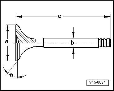
→ Fig. 3    Valve dimensions

Note:

Valves must not be reworked. Only lapping-in is permitted.

Dimension

Inlet valve

Exhaust valve

øa

mm

35.95

31.45

øb

mm

6.980

6.956

c

mm

89.95

89.95

α

45

45

 
N15-0272

→ Fig.4    Camshaft identification, valve timing

Identification

  • ◆ Cam base diameter: a = 52.8 mm ø
  • ◆ Identification by stamped numbers and letters on outer surface of exhaust valve cam of cylinder 3:

Cylinder 3 -arrow-

858 C

Valve timing at 1 mm valve lift

Inlet opens ATDC

15.8°

Inlet closes ABDC

25.3°

Exhaust opens BBDC

28.2°

Exhaust closes BTDC

18.7°

Reworking valve seats > < Removing, installing and tensioning toothed belt