
Polo Mk3
|
Removing and installing gearbox
Removing and installing gearbox
|
 |
|
|
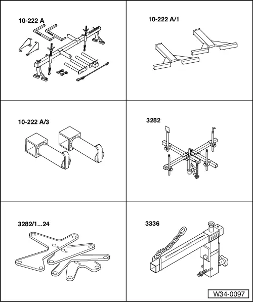
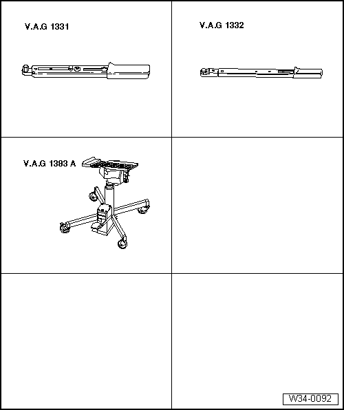
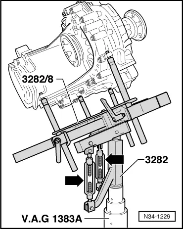
Special tools and workshop equipment required
|
 |
|
|
Special tools and workshop equipment required
Removing
|
 |
|
|
 |
|
|
 |
|
Note: Do not depress clutch pedal.
|
 |
|
|
 |
|
|
 |
|
=> Repair group 27; Removing and installing starter.
|
 |
|
|
 |
|
|
 |
|
|
 |
|
Note: Ensure the sump does not lie against the assembly mounting when lowering the engine/gearbox assembly. |
 |
|
|
 |
|
 |
|
|
 |
|
|
 |
|
|
 |
|
Note: Do not damage P.A.S pipe when lowering gearbox. |
 |
|
|
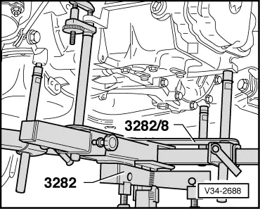
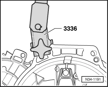
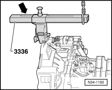
Transporting the gearbox
|
 |
|
No. of holes visible = 5 |
 |
|
|
Installing Notes:
|
 |
|
The clutch plate must be able to slide lightly to and fro on the input shaft.
|
|
|
|
|
|
|
|
|
Note: Do not damage P.A.S pipe.
|
|
|
|
|
|
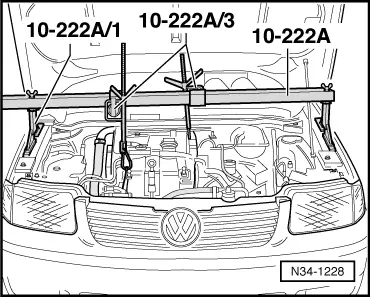
Warning!
Do not remove support bar 10-222A until the bolts securing the left-hand gearbox console have been tightened to torque setting.
|
|
|
=> Repair group 26; Removing and installing parts of the exhaust system. |
|
|
|
 |
|
|
|
|
|
|
|
|
|
|
|
|
|
|
|
|
=> General body repairs, exterior; Repair group 55; Bonnet
Note: Note radio coding for vehicles with coded radio.
Tightening torques |
 |
|||||||||||||||||||||||||
|
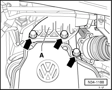
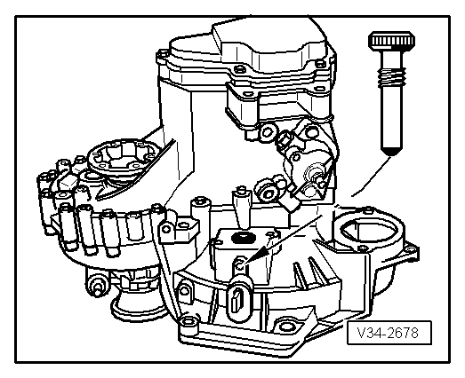
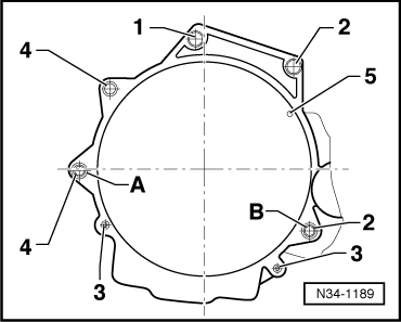
→ Gearbox to engine
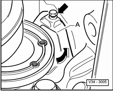
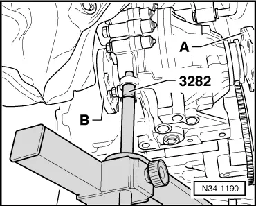
1) Stud with drive 2) Also starter to gearbox 3) Small cover plate for flywheel Items A + B - Dowel sleeves |
|
||
|
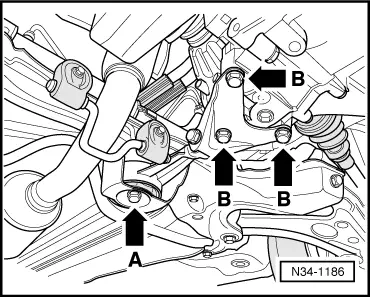
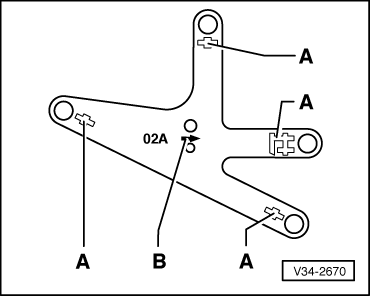
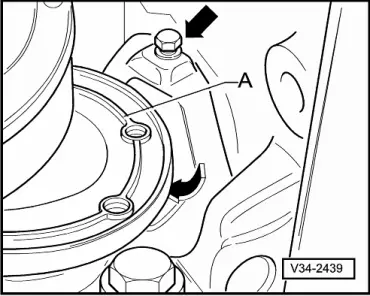
→ Gearbox console -A- to gearbox
|
|
||
|
→ Gearbox to body
|
|
||||||||||||||||
|
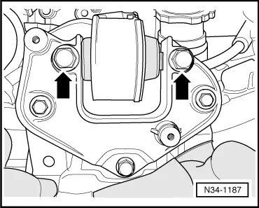
→ Rear gearbox mounting
Note: Install engine/gearbox mountings stress-free. => Repair group 10; Removing and installing engine.
| ||||||||||||||||