volkswagen Workshop Repair Guides

Volkswagen Workshop Service and Repair Manuals

Accelerator mechanism: 10.99 > (Engine codes AGD, AKU, ASX) > < Checking accelerator pedal position sender adjustment
4-cyl. Diesel engine, Mechanics
Accelerator mechanism: > 09.99 (Engine codes AGD, AHG, AKU)
Checking accelerator pedal position sender
 
W20-0052

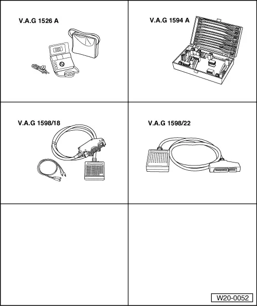
Special tools, workshop equipment, test and measuring appliances and auxiliary items required

  • ◆ V.A.G 1526 A Hand multimeter or multimeter V.A.G 1715
  • ◆ V.A.G 1594 A Adapter set
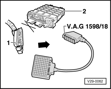
  • ◆ V.A.G 1598/18 Test box
    for 68-pin control unit
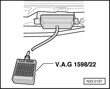
  • ◆ V.A.G 1598/22 Test box
    for 80-pole control unit
  • ◆ Fault reader V.A.G 1551 or vehicle system tester V.A.G 1552 with cable V.A.G 1551/3
  • ◆ Current flow diagram

Function

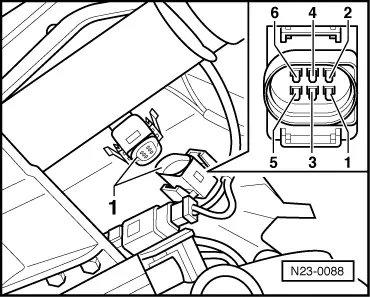
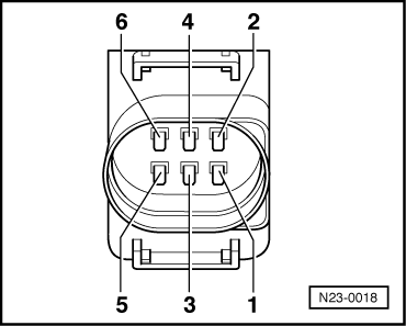
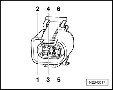
The accelerator pedal position sender is located on accelerator pedal and passes driver's requirement (pedal position) on further to the control unit.

 
N24-0831

Check conditions

  • ● Fuses must be OK.
  • ● The battery voltage must be at least 11.5 V.

Test sequence

  • ‒ Connect fault reader V.A.G 1551 (V.A.G 1552) and with ignition switched on select engine electronics control unit with the "Address word" 01:

=> Repair group 01; Self-diagnosis; Connecting fault reader V.A.G 1551 and selecting engine electronics control unit

 
→ Indicated on display:
Rapid data transfer     HELP
Select function XXX
  • ‒ Press keys 0 and 8 for the function "Read measured value block" and confirm entry with Q key.
 
→ Indicated on display:
Read measured value block
Input display group number XXX
  • ‒ Press keys 0, 0 and 2 for "Display group number 2" and confirm entry with Q key.
 
→ Check accelerator pedal position display in display zone 2. The accelerator pedal must not be depressed.
     Specification: 0.0 %
Read measured value block 2     ⇒
0 rpm     0.0 %     0     1     0     18.4 5C
  • ‒ Also check the idling speed switch display in display zone 3. The centre position must show 1.
         Display: 0 1 0
  •  
    → Slowly depress accelerator pedal until fully down and observe display zones 2 and 3.
    Read measured value block 2     ⇒
    0 rpm     100.0 %     0     0     0          18.4 5C
    • ‒ Display zone 2:
      The accelerator pedal position figure must increase continuously.
           Specification at full throttle position: 100.0 %
    • ‒ Display zone 3:
      The centre position must change to 0.
           Display: 0 0 0

    End specification value not achieved:

    • ‒ Adjust accelerator pedal position sender
      =>Page 20-23

    Display does not change or is erratic:

    • ‒ Check accelerator pedal position sender wiring as follows:
    • ‒ Press the ⇒key.
     
    N23-0088
    • ‒ Press keys 0 and 6 for the function "End output" and confirm entry with the Q key.
    • ‒ Switch off ignition.
    • ‒ Remove cover in footwell (driver's side).
    • ‒ → Disconnect 6-pin connector -1- for accelerator pedal position sender.
     
    N23-0018
    • ‒ → Measure sender resistance between connector contacts 1+3.
           Specification:
           Accelerator pedal in idling speed position: 1.0...1.5 kω
           Accelerator pedal in full throttle position: 1.5...2.5 kω
    • ‒ Measure resistance between connector contacts 4+6.
           Specification:
           Accelerator pedal in idling speed position: max.1.5 kω
           Accelerator pedal depressed: ∞ ω

    If the specifications are not obtained:

    • ‒ Replace accelerator pedal position sender (G79)
      =>Page 20-20 , item 2 .

    If the specifications are obtained:

    Engine code AGD (with 68 pin control unit)

     
    V29-0062
    • ‒ → Connect test box V.A.G 1598/18 to control unit wiring harness -1-. The engine control unit -2- remains disconnected.
     
    N23-0017
    • ‒ → Check wiring between test box and connector for open circuit according to current flow diagram.
           Contact 1+ socket 15
           Contact 2+ socket 57
           Contact 3+ socket 55
           Contact 4+ socket 65
           Contact 5+ socket 62
           Contact 6+ socket 33
           Wire resistance: max. 1.5 ω
     
    N23-0197

    Engine codes AGD (with 80-pin control unit), AHG, AKU

    • ‒ → Connect test box V.A.G 1598/22 to control unit wiring harness.
     
    N23-0017
    • ‒ → Check wiring between test box and connector for open circuit according to current flow diagram.
           Contact 1+ socket 24
           Contact 2+ socket 11
           Contact 3+ socket 23
           Contact 4+ socket 12
           Contact 5+ socket 8
           Contact 6+ socket 25
           Wire resistance: max. 1.5 ω

    Continued for all engine codes

    • ‒ Additionally check the wiring for short to battery positive or earth.
    • ‒ Additionally check wires for short to one another.

    If no fault is detected in the wiring:

    • ‒ Renew engine control unit:

    => Repair group 23; Renewing, coding and adapting engine control unit; Renewing engine control unit

    Accelerator mechanism: 10.99 > (Engine codes AGD, AKU, ASX) > < Checking accelerator pedal position sender adjustment