volkswagen Workshop Repair Guides

Volkswagen Workshop Service and Repair Manuals

Checking semi-automatic toothed belt tensioning roller > < Checking valve timing
4-Cyl. injection engine (4-valve, roller rocker arm), Mechanics
Dismantling and assembling engine
Removing, installing and tensioning toothed belts
 
W13-0049

Special tools, workshop equipment, test and measuring appliances and auxiliary items required

  • ◆ 10-222A Support bracket
  • ◆ 10-222A/1 Support for support bracket
  • ◆ 3415 Counter support
  • ◆ 3415/1 Pins
  • ◆ T 10016 Camshaft locking device
  • ◆ V.A.G 1331 Torque wrench (5...50 Nm)
 
W00-0428
  • ◆ V.A.G 1332 Torque wrench (40...200 Nm)

Removing

 
N24-0739
  • ‒ → Remove cover above camshaft housing -arrows-.
  • ‒ Install air cleaner:

=> Repair group 24; Servicing injection; Dismantling and assembling air cleaner

  • ‒ Remove the toothed belt guard upper part.
 
N13-0451
  • ‒ → Position the crankshaft to top dead centre No. 1 cylinder. The notch on the pulley must align with the edge of the -O- mark.
 
N13-0155
  • ‒ → The locking pin holes in the camshaft sprockets must align with the fitting holes in the camshaft housing -arrows-.

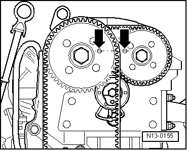
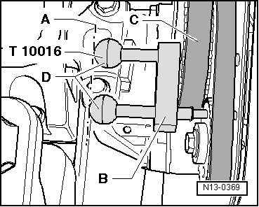
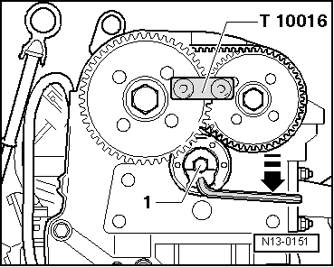
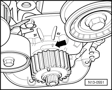
Note:

If the locking pin holes are positioned to the outside on the toothed belt sprockets, the crankshaft must be turned one revolution further.

Fix both camshaft sprockets with camshaft locking device T 10016 as follows:

 
N13-0369
  • ‒ → Guide both locking pins through camshaft sprocket locking pin holes onto stop in camshaft housing fitting holes.

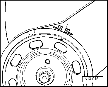
Note:

Both locking pins are inserted correctly when the ends -D- align with line -A-.

  • ‒ Slide retainer -B- onto stop on inlet camshaft sprocket -C-.

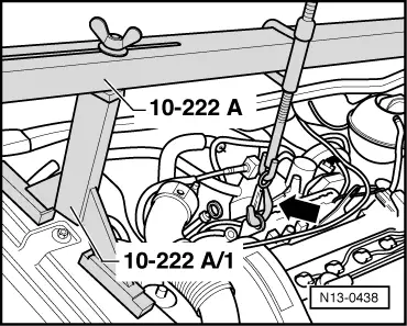
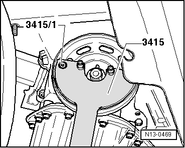
The engine must be lowered slightly as follows to enable the crankshaft sprocket to be removed:

 
N13-0438
  • ‒ → Fit support 10-222A with legs 10-222A/1 as shown.
  • ‒ Remove power assisted steering reservoir and place to side.
  • ‒ Remove upper securing bolt from lower toothed belt guard under console.
  • ‒ Take-up weight of engine, and remove console.
 
N10-0192
  • ‒ → Remove securing bolts -A- and -B-
    and remove complete assembly mounting.
  • ‒ Remove console from cylinder head.
  • ‒ Remove right insulation tray.
  • ‒ Lower engine until the pulley securing bolt is accessible.
  • ‒ Mark the direction of rotation of the ribbed belt and remove belt as follows.
 
N13-0552
  • ‒ → Using a spanner on the securing bolt swivel tensioning roller in direction of arrow.
  • ‒ Remove ribbed belt.
 
N13-0469
  • ‒ → Remove pulley and toothed belt sprocket securing bolt. To do this hold the pulley with counter-hold tool 3415 and 3415/1.
  • ‒ Remove pulley. Refit securing bolt with two washers and tighten to secure toothed belt sprocket.
  • ‒ Remove idler roller on vehicles with air conditioning system and ribbed belt tensioning roller.
  • ‒ Remove lower toothed belt guard.
  • ‒ Mark direction of rotation of both toothed belts.
 
N13-0310

Removing main drive toothed belt:

  • ‒ → Release main drive tensioner -1- and slacken toothed belt by turning tensioning roller anti-clockwise -arrow-.
  • ‒ Loosen clamping bolt on tensioning roller.
  • ‒ Take off toothed belt.

Removing coupling drive toothed belt:

 
N13-0151
  • ‒ → Loosen coupling drive tensioner -1- and slacken toothed belt by turning tensioning roller clockwise.
  • ‒ Remove coupling drive tensioning roller.
  • ‒ Take off toothed belt.

Installing

Prerequisites

  • ● The pistons must not be positioned at TDC.
  • ● The crankshaft toothed belt sprocket is secured to the crankshaft with the securing bolt and two washers.
  • ● Camshaft sprockets arrested in camshaft housing fitting holes with T 10 016 and secured against turning.

Note:

If a piston is at TDC the valves could strike the piston when turning the camshafts.

 
N13-0551

Work sequence

  • ‒ → Set the crankshaft to TDC No. 1 cylinder. The tooth with end ground down must align with the mark on the oil pump -arrow-.
  • ‒ Fit toothed belt for coupling the camshafts in a clockwise direction starting at top on inlet camshaft sprocket and then onto exhaust camshaft sprocket. The slack section of the toothed belt must be downwards. Note direction of rotation with used belts.

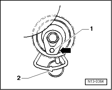
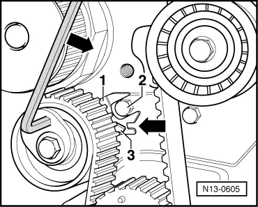
Install coupling drive tensioning roller as follows:

 
N13-0364
  • ‒ → Turn coupling drive tensioning roller clockwise towards marking window -arrow- using a hexagon key -1- (tensioning roller in untensioned position).
  • ‒ Press lower section of toothed belt for coupling the camshafts upwards with tensioning roller and fit tensioning roller securing bolt.
 
N13-0365
  • ‒ Tighten securing bolt hand tight. The lug in the base plate must engage in the hole in the cylinder head -2-.
  • ‒ → Then tension toothed belt by turning tensioning roller anti-clockwise, with a hexagon key item -1-, until the indicator -2- aligns over the lug in the base plate in the marking window -arrow-.
  • ‒ Tighten clamping nut on tensioning roller.
         Tightening torque: 20 Nm

Note:

The tool must secure camshaft against turning until the main drive toothed belt is fitted.

  • ‒ Fit main drive toothed belt on in anti-clockwise direction starting at water pump then via tensioning roller, crankshaft, idler roller and inlet camshaft sprocket. Note direction of rotation with used belts.

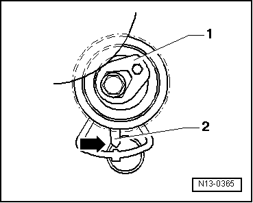
If tensioning roller was removed beforehand, install tensioning roller as follows:

 
N13-0366
  • ‒ → Using Allen key turn main drive tensioning roller anti-clockwise to position shown -arrow-.
 
N13-0605
  • ‒ → Tighten securing bolt hand tight. The base plate -1- cut-out must engage over securing bolt -2-.
  • ‒ Loosen securing bolt on used tensioning roller.
  • ‒ Then tension toothed belt by turning the tensioning roller in direction of arrow until the indicator -3- aligns with the groove in the base plate -arrow-.
  • ‒ Remove tool from camshaft sprockets.
  • ‒ Tighten clamping nut on tensioning roller.
         Tightening torque: 20 Nm
  • ‒ Now turn the crankshaft two turns in engine direction of rotation until it is again at top dead centre No. 1 cylinder.
  • ‒ Now the position of the toothed belts and tensioning roller must be checked again.
  • ‒ Tension toothed belt again if necessary.
  • ‒ Refit toothed belt guard.
  • ‒ Refit crankshaft belt pulley. When doing this note the following:
    • ‒ The securing bolt for the pulley and toothed belt sprocket must be renewed.
    • ‒ When installing the pulley observe the fixing arrangement to toothed belt sprocket.
    • ‒ Tightening procedure for the new oiled bolt: 90 Nm + 1/4 turn (90°) further.
  • ‒ Fit console on cylinder head.
  • ‒ Install engine mounting.

Tightening torques

 
N10-0192

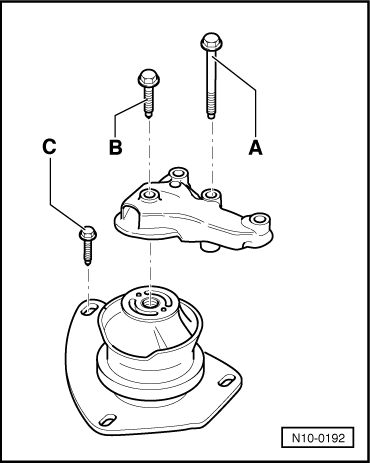
Note:

The assembly mounting securing bolts are stretch bolts and must be replaced.

→ Engine mounting

A = 40 Nm + 1/4 turn (90°) further
B = 50 Nm
C = 20 Nm + 1/8 turn (45°) further

  • ‒ Install power assisted steering reservoir.
  • ‒ Install ribbed belt again.

Note:

When installing the ribbed belt ensure that it sits correctly in the pulleys.

  • ‒ Interrogate fault memory:

=> Repair group 01; Fault memory; Interrogating and erasing fault memory of engine control unit

Checking semi-automatic toothed belt tensioning roller > < Checking valve timing