volkswagen Workshop Repair Guides

Volkswagen Workshop Service and Repair Manuals

Piston and cylinder dimensions > < Crankshaft dimensions
4-Cyl. injection engine (4-valve, roller rocker arm), Mechanics
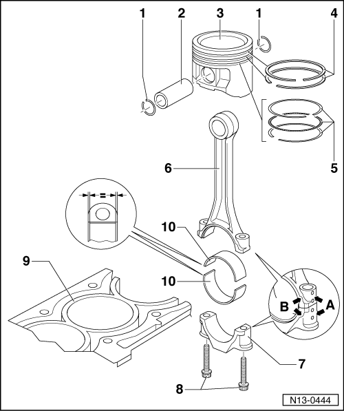
Dismantling and assembling pistons and conrods
 
N13-0444
  • Circlip
  • Piston pin
    • ◆ If difficult to remove, heat piston to 60 °C
    • ◆ Remove and install with drift 10-14
  • Piston
    • ◆ Checking => Fig. 3
    • ◆ Mark installation position and cylinder number
    • ◆ Arrow on piston crown points to pulley end
    • ◆ Install using piston ring clamp
 
N13-0444
  • Compression rings
    • ◆ Offset gaps by 120 °
    • ◆ Remove and install compression rings with piston ring pliers
    • ◆ "TOP" faces towards piston crown
    • ◆ Checking ring gap=> Fig. 1
    • ◆ Checking ring to groove clearance
      => Fig. 2
  • Oil scraper rings
    • ◆ Carefully remove and install 3-part oil scraper rings by hand
    • ◆ Checking ring gap=> Fig. 1
    • ◆ Checking ring to groove clearance
      => Fig. 2
  • Conrod
    • ◆ Only renew as a set
    • ◆ Mark cylinder number -A-
    • ◆ Installation position:
      Marking -B- faces towards pulley end
    • ◆ Guided axially via piston
 
N13-0444
  • Conrod bearing cap
    • ◆ The caps only fit in one position and only on the appropriate con-rod, this is due to the breaking procedure (cracking) separating the cap from the con-rod
  • Conrod bolt, 20 Nm + 1/4 turn (90 °) further
    • ◆ Renew
    • ◆ Oil threads and contact surface
    • ◆ To measure radial clearance tighten to 20 Nm but not further
  • Cylinder block
    • ◆ Checking cylinder bores
      =>Fig. 4
    • ◆ Piston and cylinder dimensions
 
N13-0444
  • Bearing shell
    • ◆ Do not interchange used bearing shells
    • ◆ Measure pretension
      => Fig. 5
    • ◆ Insert bearing shells centrally
    • ◆ Check radial clearance with Plastigage:
      New: 0.020...0.061 mm
      Wear limit: 0.091 mm
      Do not rotate crankshaft when checking radial clearance
 
V13-0016

→ Fig. 1     Checking piston ring gap

  • ‒ Push ring squarely from above down to approx. 15 mm from bottom end of cylinder.

Piston ring
Dimensions in mm

New

Wear limit

1. Compression ring

0.20...0.50

1.0

2. Compression ring

0.40...0.70

1.0

Oil scraper ring

0.25...0.50

---1)

     1)     No wear limit details

 
V13-0687

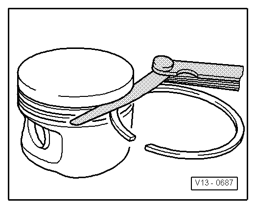
→ Fig. 2     Checking ring to groove clearance

Clean groove before check.

Piston ring
Dimensions in mm

New

Wear limit

1. Compression ring

0.04...0.08

0.15

2. Compression ring

0.02...0.06

0.15

Oil scraper ring

Cannot be measured

 
V13-0010

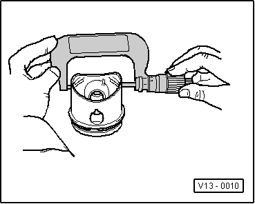
→ Fig. 3     Checking piston

Special tools, workshop equipment, testers, measuring instruments and auxiliary items required

  • ◆ Micrometer 75...100 mm
  • ‒ Approx. 10 mm from lower edge and offset 90 ° to piston pin axis. Deviations from nominal dimensions
         max. 0.04 mm
  • Nominal dimension ; Piston and cylinder dimensions
 
V13-0280

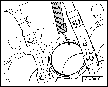
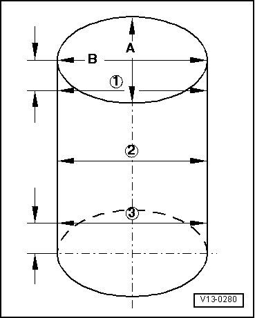
→ Fig. 4     Checking cylinder bores

Special tools, workshop equipment, testers, measuring instruments and auxiliary items required

  • ◆ Internal dial gauge 50...100 mm
  • ‒ Take measurements at 3 positions in both lateral -A- and longitudinal -B- directions, as illustrated. Deviation from nominal dimension
         max. 0.08 mm
  • Nominal dimension => Page 13-64 ; Piston and cylinder dimensions

Note:

Measuring the cylinder bores must not be done when the cylinder block is mounted on a repair stand with adapter bracket VW 540, as incorrect measurements would then be possible.

 
N13-0015

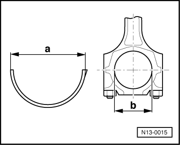
→ Fig. 5     Measuring bearing shell pretension

Special tools, workshop equipment, testers, measuring instruments and auxiliary items required

  • ◆ Vernier caliper

The bearing shell pretension is calculated as follows:

     Bearing shell dimension -a-
-     Conrod diameter -b-
=     Pretension

Minimum dimension: 1.5 mm

If the pretension is not achieved:

  • ‒ Renew bearing shells.

Piston and cylinder dimensions > < Crankshaft dimensions