-
‒ →
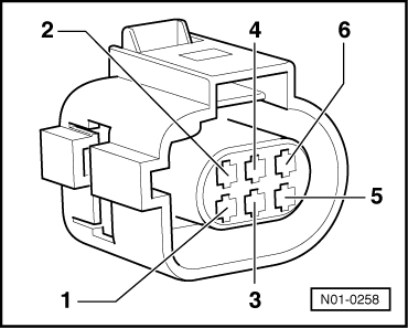
Check wiring for open circuit between test box and 6-pin connector using current flow diagram.
Contact 2 and test box socket 98
Contact 4 and test box socket 108
Contact 6 and test box socket 100
Wire resistance: max. 1.5ω
-
‒ Additionally check wiring for short to one another, and for short to positive or earth.
If the specification is obtained:
-
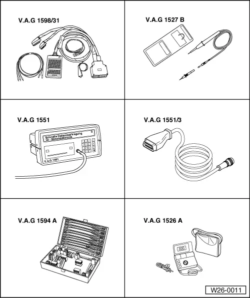
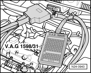
‒ Connect engine control unit to test box V.A.G 1598/31 and reconnect 6-pin connector to EGR valve.
-
‒ Connect the fault reader V.A.G 1551 (V.A.G 1552). Then switch ignition on and select engine control unit with the "Address word" 01.
=> Repair group 01; Self-diagnosis general: Connecting fault reader V.A.G 1551 and selecting engine electronics control unit.
-
‒ Initiate final control diagnosis and select EGR valve (N18):
=> Repair group 01; Final control diagnosis; Performing final control diagnosis
-
‒ Connect diode test lamp V.A.G 1527 B to test box socket 100 and earth using adapter from V.A.G 1594.
The LED must flash.
-
‒ Proceed with final control diagnosis until completed.
-
‒ Press keys 0 and 6 for the "End data transfer" function and confirm input with the Q key.
-
‒ Switch off ignition.
-
‒ Depending on conditions, renew following components:
LED flashes:
-
‒ Renew EGR valve (N18) with potentiometer (G212).
-
‒ Erase learnt values and re-adapt engine control unit
=> Repair group 24; Engine control unit; Erasing learnt values and adapting engine control unit to throttle valve control part and EGR valve
If no wiring fault is detected and the LED does not flash:
-
‒ Renew engine control unit.
=> Repair group 24; Engine control unit; Renewing engine control unit
|