volkswagen Workshop Repair Guides

Volkswagen Workshop Service and Repair Manuals

Accelerator mechanism > < Crash fuel shut-off
4-Cyl. injection engine (4-valve, roller rocker arm), Mechanics
Removing and installing parts of fuel supply system
Checking fuel pump
 
W20-0015

Special tools, workshop equipment, test and measuring appliances and auxiliary items required

  • ◆ 3217 Spanner for union nut
  • ◆ V.A.G 1318 Pressure gauge
  • ◆ V.A.G 1318/1 Adapter
  • ◆ V.A.G1318/7 Adapter
  • ◆ V.A.G 1318/11 Adapter
  • ◆ V.A.G 1318/13 Adapter
 
W20-0018
  • ◆ V.A.G1318/17 Adapter
  • ◆ V.A.G 1332 Torque wrench (40...200 Nm)
  • ◆ V.A.G 1348/3 A Remote control
  • ◆ V.A.G 1348/3-2 Adapter cable
  • ◆ V.A.G 1527 B Diode test lamp
  • ◆ V.A.G 1594 A Adapter set
 
W00-0573
  • ◆ V.A.G 1715 Multimeter
  • ◆ Measuring container
  • ◆ Current flow diagram

Test conditions

  • ● Battery voltage at least 11.5 V
 
N24-0876
  • ● → Fuse No. SB40 OK.

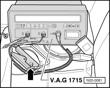
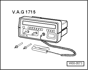
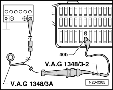
Checking function and voltage supply

Note:

Check whether a coded radio is installed as during the forthcoming work sequences the battery earth strap must be disconnected. Obtain radio code first if necessary.

  • ‒ Fold rear seat forwards.
  • ‒ Remove floor cover.
  • ‒ Briefly operate starter. Fuel pump must be heard to run           briefly -approx. 1 second-.

If the fuel pump does not run:

 
N20-0365
  • ‒ Switch off ignition.
  • ‒ Remove cover in front of fuse holder.
  • ‒ → Pull fuse No. SB40 out of fuse holder.
  • ‒ → Connect remote control V.A.G 1348/3A with adapter cable V.A.G 1348/3-2 on contact 40b to fuel pump and battery positive (+).
  • ‒ Operate remote control.

Fuel pump runs:

 
N20-0348
  • ‒ Check activation of fuel pump relay:

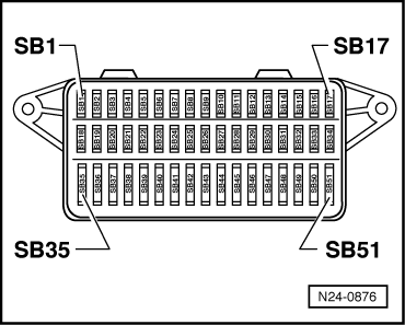
=> Current flow diagrams, Electrical fault finding and Fitting locations

Fuel pump does not run:

  • ‒ → Pull 4-pin connector -1- off fuel tank flange -2-.
 
N20-0348
  • ‒ → Connect diode test lamp V.A.G 1527 using adapter cables from V.A.G 1594 to the outer contacts of the connector.
  • ‒ Operate remote control.
         LED must light up

LED does not light up:

  • ‒ Locate and eliminate open circuit using current flow diagram

LED lights up (voltage supply OK.):

  • ‒ Fit spanner 3217 on the three rounded ribs of union nut and unscrew union nut from flange.
  • ‒ Check that the electrical wires between flange and fuel pump are connected.

If not open circuit can be found:

  • ‒ Renew fuel delivery unit.

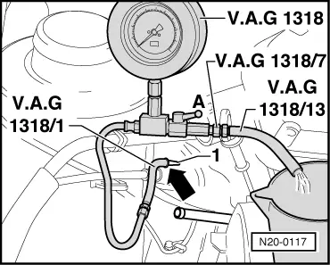
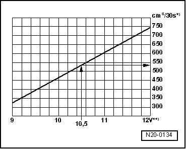
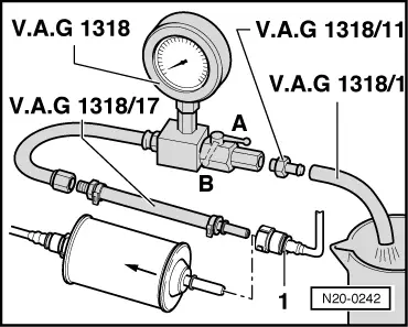
Checking delivery rate

Test conditions

  • ● The voltage supply for the fuel pump OK.
  • ● Remote control V.A.G 1348/3A is still connected.

Test sequence

  • ‒ Remove filler cap from fuel tank filler neck.
Warning!
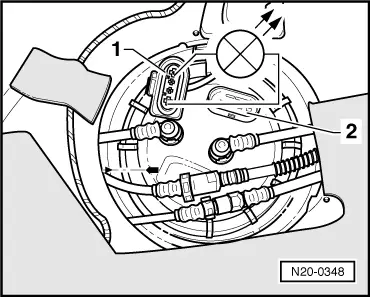
Fuel supply lines are under pressure! Before removing from hose connection wrap a cloth around the connection. Then release pressure by carefully pulling hose off connection.
 
N20-0117
  • ‒ → Pull fuel supply hose (white marking) off fuel supply pipe -1-.
  • ‒ Connect pressure gauge V.A.G 1318 with adapter /1 to fuel supply pipe.
  • ‒ Screw adapter hose /13 with adapter /7 to pressure gauge and hold hose in measuring container.
  • ‒ Open the pressure gauge shut-off tap. The lever then points in the direction of flow -A-.
  • ‒ Operate remote control V.A.G 1348/3A and slowly close cut-off tap, until pressure gauge shows
         3 bar.
    From this point on do not move position of cut-off tap.
  • ‒ Empty the measuring container.
  • ‒ The fuel pump delivery range is dependent upon battery voltage. Therefore connect the multimeter with adapter cables from V.A.G 1594 to the vehicle battery.
 
N20-0134
  • ‒ Operate remote control for
         30 seconds
    and measure battery voltage
  • ‒ → Compare the quantity of fuel delivered with specification.

     *)     Minimum delivery cm3/30 seconds

     **)     Voltage at fuel pump with engine stopped and pump running (approx. 2 volts less than battery voltage).

Example:

During the test, a voltage of 12.5 volts is measured at the battery. As the voltage at the pump is approx. 2 volts less than the battery voltage, this will equate to a minimum delivery of 540 cm3/30 s.

If the minimum delivery rate is not attained:

  • ‒ Check the fuel pipes for possible restrictions (kinks) or blockages.
 
N20-0242
  • ‒ → Pull supply hose -1- off inlet to fuel filter.
  • ‒ Connect pressure gauge V.A.G 1318 with adapter 1318/17 to fuel supply pipe.
  • ‒ Repeat delivery rate check.

If the minimum delivery rate is now attained:

  • ‒ Replace the fuel filter.

If the minimum delivery rate is again not attained:

  • ‒ Remove the fuel delivery unit and check the strainer filter for soiling.

Only when up to now no fault has been detected:

  • ‒ Replace the fuel delivery unit.

If the delivery rate has been attained but nevertheless you suspect a fuel supply system fault (e.g. intermittent failure of fuel supply system):

  • ‒ Check the current draw of the fuel pump as follows:
  • ‒ Reconnect all disconnected fuel pipes.
 
N20-0061
  • ‒ → Connect the multimeter V.A.G 1715 using the current clamp to the red/yellow wire from wiring harness.
  • ‒ Start the engine and run at idling speed.
  • ‒ Measure the current draw of the fuel pump.
         Specification: max. 8 amps.

Note:

If the fuel system malfunction is intermittent, you can perform the check during a test drive with the help of a 2nd person.

If the current draw is exceeded:

  • ‒ Replace the fuel delivery unit.

Checking fuel pump non-return valve

Test conditions

  • ● Remote control V.A.G 1348/3A is still connected.
  • ● Pressure gauge V.A.G 1318 is still connected.

Test sequence

Note:

With this check the fuel supply pipe connections from the fuel delivery unit to the point at which the pressure gauge V.A.G 1318 is connected will be checked for leaks at the same time.

  • ‒ Close pressure gauge cut-off tap (lever at right angle to direction of flow).
  • ‒ Operate remote control at short intervals until a pressure of
         3 bar
    has built up.
Warning!
Danger of spray when opening the shut-offtap, hold container over the free connection of the pressure gauge.
  • ‒ If pressure builds up too high, lower excess pressure by carefully opening the shut-off tap.
  • ‒ Watch pressure drop. After 10 minutes the pressure must not drop below
         2 bar.

If the pressure drops further:

  • ‒ Check pipe connections for leaks.

If no fault is detected in the wiring:

  • ‒ Replace the fuel delivery unit.

Accelerator mechanism > < Crash fuel shut-off