volkswagen Workshop Repair Guides

Volkswagen Workshop Service and Repair Manuals

Securing engine to assembly stand > < Removing and installing engine
4-Cyl. injection engine (4 valve, roller rocker finger), Mechanics
Removing and installing engine
Notes on removing
  • ‒ First check whether a coded radio is fitted. If this is the case obtain the anti-theft coding.
  • ‒ The engine is removed forwards together with the gearbox.
  • ‒ With ignition switched off disconnect battery earth strap.
  • ‒ Removing front bumper:

=> General body repairs, Repair group 63; Front bumper, removing and installing front bumper

  • ‒ Bring lock carrier into service position:

=> General body repairs; Repair group 50; Body front; lock carrier service position

  • ‒ All cable ties which are opened or cut open when removing engine, must be replaced in the same position when installing engine.
  • ‒ Open and close the expansion tank sealing cap to release pressure in cooling system.
 
A10-0116
  • ‒ → Remove battery and battery retainer.
  • ‒ Unclip cable guide -from battery to bulkhead-.
  • ‒ Release plus wire from battery to starter motor (is removed together with assembly).
  • ‒ Unclip accelerator cable from air cleaner upper part.
  • ‒ Detach the accelerator cable from the support bracket and the throttle valve control part (do not remove locating clip).
  • ‒ Remove air cleaner:

=> Repair group 24; Servicing injection; Dismantling and assembling air cleaner
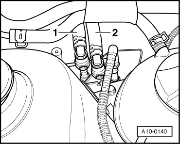
 
A10-0140
  • ‒ → Now separate fuel supply as well as fuel return pipes -item 1 and 2- (press release button).
Warning!
Fuel supply lines are under pressure! Before removing from hose connection wrap a cloth around the connection. Then release pressure by carefully pulling hose off connection.
  • ‒ Loosen or separate the following components:
    • ‒ The hose from intake manifold to activated charcoal filter system
    • ‒ The vacuum hose from inlet manifold to brake servo
    • ‒ The connector from engine speed sender below oil dipstick tube bracket, and pull connector out from retainer
    • ‒ The connector from ignition transformer, from Hall sender and throttle valve control part
    • ‒ The connector from coolant temperature sender, oil pressure switch and exhaust gas recirculation valve
    • ‒ Injector connectors

Vehicles with manual gearbox

  • ‒ Disconnect selector mechanism from gearbox.

=> 5-Speed manual gearbox 02K; Repair group 34; Servicing selector mechanism

Vehicles with automatic gearbox

  • ‒ Remove selector lever cable from gearbox:

=> Automatic gearbox 01M; Repair group 37; Servicing shift mechanism; Dismantling and assembling shift mechanism

Continuation for all vehicles

  • ‒ Remove noise insulation tray:

=> General body repairs; Repair group 50; Front body; Removing insulation tray

  • ‒ Loosen or separate the following components:
    • ‒ Lambda probe connector
    • ‒ The 2 pin connector from knock sensor (rear of cylinder block) and the 4 pin connector from intake manifold pressure sender front right below intake manifold
  • ‒ Drain coolant .
  • ‒ Loosen hose clips and pull coolant hoses off coolant thermostat housing.
  • ‒ Loosen belt pulley securing bolts from power steering vane pump.
  • ‒ Remove ribbed belt => Page 13-11 .
  • ‒ Unbolt power steering vane pump and secure to sub-frame with wire; hoses remain connected:

=> Running gear; Repair group 48; Assembly overview: vane pump, reservoir, hydraulic lines; Removing and installing power steering vane pump.

Vehicles with air conditioner

  • ‒ Removing air conditioner compressor:
  • ‒ Observe additional information and removal instructions =>Page10-15

Vehicles with manual gearbox

  • ‒ Remove hydraulic clutch slave cylinder:

=> 5-Speed manual gearbox 02K; Repair group 30; Servicing clutch control

Note:

Clutch pedal must not be depressed.

Continuation for all vehicles

  • ‒ Pull radiator coolant hoses off engine using hose clip pliers V.A.G 1921.
 
A37-0200
  • ‒ → Disconnect pendulum support -arrows-.
  • ‒ Pull vacuum and breather hoses off engine.
  • ‒ Disconnect all electric wires from gearbox, alternator and starter and move clear.
  • ‒ Separate front exhaust pipe from exhaust manifold => Page 26-2 , exhaust manifold, front exhaust pipe and catalyst with attachments.
  • ‒ Remove securing clamps for power steering pressure pipe.
  • ‒ Pull off/disconnect all other electrical connections as necessary from engine and lay to one side.
  • ‒ Remove left and right-hand drive shaft on gearbox and tie up:

=> Running gear; Repair group 40; Removing and installing drive shaft
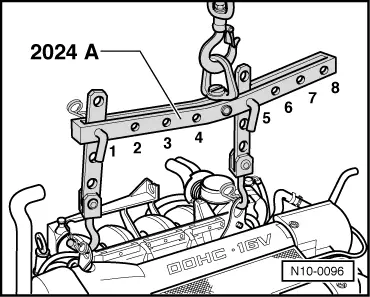
 
N10-0096
  • ‒ → Attach lifting tackle 2024 A as follows and lift slightly with workshop crane:

     Pulley end:
     3rd hole in hook at position 1

     Flywheel end:
     3rd hole in hook at position 5

Warning!
The hooks and locating pins must be secured with locking pins.

Notes:

  • ◆ The positions marked 1...4 on the bar must be towards the pulley end.
  • ◆ The holes in the hook rails are counted up from the hook.
  • ‒ Remove coolant system expansion reservoir and lay to one side.
  • ‒ Remove power steering reservoir and tie up.
 
N10-0192
  • ‒ Remove activated charcoal filter.
  • ‒ → Remove engine mounting. To do this unscrew bolts -A, B and C-.
 
N10-0028
  • ‒ → Remove gearbox mounting. To do this unscrew bolts -A, B and C-.

Turn assembly slightly to left (engine forwards, gearbox rearwards) and lift engine carefully out forwards.

Note:

When the assembly is lifted off, it must be carefully guided to prevent damage to the bodywork.

Securing engine to assembly stand > < Removing and installing engine