volkswagen Workshop Repair Guides

Volkswagen Workshop Service and Repair Manuals

READINESS code > < Final control diagnosis
4LV injection and ignition system
Final control diagnosis
Performing final control diagnosis

The final control diagnosis activates the following components in the stated sequence:

1. Throttle valve positioner (V60)

2. Activated charcoal filter solenoid valve 1 (N80)

3. Exhaust gas recirculation valve (N18)

4. Engine speed signal1)

5. Fuel pump relay (J17)

6. Engine/air conditioner compressor electrical connection1)

     1)     not relevant

Special tools, workshop equipment, testers, measuring instruments and auxiliary items required

  • ◆ Fault reader V.A.G 1551 or vehicle system tester V.A.G 1552 with cable V.A.G 1551/3A
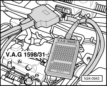
  • ◆ Test box V.A.G 1598/31
  • ◆ Hand multimeter V.A.G 1526 or multimeter V.A.G 1715
  • ◆ Diode test lamp V.A.G 1527
  • ◆ Adapter set V.A.G 1594
  • ◆ Current flow diagram

Check conditions

 
N24-0831
  • ● → The fuses No. 1, 3, 11, 16, 23, 24, 27, 28, 30, 31, 32, 34, 36, 37 and 40 must be OK.
  • ● The battery voltage must be at least 11.5 V.
  • ● All electrical consumers, e.g. lights and rear window heating must be switched off.
  • ● Throttle valve potentiometer (G69) OK.

Notes:

  • ◆ The final control diagnosis can only be carried out if the engine is stationary and ignition switched on.
  • ◆ The final control diagnosis will be aborted if the engine is started or a rotational impulse is recognised.
  • ◆ During the final control diagnosis the individual final controls will be activated until advancing to the next final control by pressing the ⇒ button.
  • ◆ The final controls are checked acoustically or by touching.

Work sequence

  • ‒ Connect the fault reader V.A.G 1551 (V.A.G 1552). Then switch ignition on and select engine control unit with the "Address word" 01.
    (Connecting fault reader and selecting engine control unit .)
 
→ Indicated on display:
Rapid data transfer     HELP
Select function XX
  • ‒ Operate fault reader taking into account the information on the display:
  • ‒ Press keys 0 and 3 for the function "Final control diagnosis".
 
→ Indicated on display:
Rapid data transfer     Q
03 Final control diagnosis

Activating throttle valve positioner (V60):

  • ‒ Confirm input with Q key.
 
→ Indicated on display:
Final control diagnosis     ⇒
Throttle valve positioner-V60
  • The throttle valve positioner must open and close the throttle valve until switching to the next final control by pressing the ⇒key.

If the throttle valve positioner does not move:

  • ‒ Check throttle valve positioner
    , Checking throttle valve control part.

Activating activated charcoal filter solenoid valve 1 (N80):

  • ‒ Press ⇒key.
 
→ Indicated on display:
Final control diagnosis     ⇒
Activ. charcoal filter solenoid valve 1     -N80
  • The solenoid valve (right-hand suspension turret) must click, until activating the next final control element by pressing ⇒key.
  • ‒ Pull hose off activated charcoal filter at solenoid valve.
  • ‒ Connect an auxiliary hose to the vacant valve connection.
  • ‒ Blow into auxiliary hose during final control diagnosis (in direction of throttle valve control part).
         Valve must open and close

If the solenoid valve does not click:

  • ‒ Continue check => Page 01-68 .

Activating exhaust gas recirculation valve (N18):

  • ‒ Press ⇒key.
 
→ Indicated on display:
Final control diagnosis     ⇒
Exhaust gas recirculation valve -N18
  • The exhaust gas recirculation valve (engine compartment, left, on cylinder head) must click until the next final control is activated by pressing the ⇒key.

If the exhaust gas recirculation valve does not click:

  • ‒ Continue check => Page 01-70 .

Activating fuel pump relay (J17):

  • ‒ Press ⇒key twice.
 
→ Indicated on display:
Final control diagnosis     ⇒
Fuel pump relay J17
  • The fuel pump relay (on the relay plate) must click until the next final control is activated by pressing the ⇒key.

Note:

During the activation of the fuel pump relay (on relay plate), the fuel pump must be heard to run at intervals. Do not activate door contact switch during the test.

If the relay does not click:

  • ‒ Check fuel pump relay:

=> Current flow diagrams, Electrical fault finding and Fitting locations

  • ‒ Press ⇒key twice.
 
→ Indicated on display:
Rapid data transfer     HELP
Select function XX
  • ‒ Press keys 0 and 6 for the "End output" function and confirm input with the Q key.
 
→ Indicated on display:
Rapid data transfer     HELP
Enter address word XX
  • ‒ Switch off ignition.

Continuation of check when the activated charcoal filter solenoid 1 does not click:

 
N24-0833
  • ‒ → Pull the 2 pin connector off solenoid valve 1 (N80) -arrow-.
 
N24-0767
  • ‒ → Connect diode test lamp V.A.G 1527 using adapter cables from V.A.G 1594 to detached connector.
         The LED must flash (bright/darker)

LED flashes:

  • ‒ Proceed with final control diagnosis until completed.
  • ‒ Switch off ignition.
  • ‒ Replace solenoid valve 1 (N80):

=> Repair group 20; Activated charcoal filter system; Removing and installing parts of activated charcoal filter system

LED does not flash:

  • ‒ Proceed with final control diagnosis until completed.
  • ‒ Switch off ignition.
 
N24-0943
  • ‒ → Connect test box V.A.G 1598/31 to control unit wiring harness. The engine control unit remains disconnected.
 
A24-0090
  • ‒ → Check wire for open circuit between test box socket 64 and 2-pin connector contact 2 using current flow diagram.
         Wire resistance: max. 1.5 ω
  • ‒ Additionally check wire for short to battery positive and earth.
         Specification: ∞ω
  • ‒ Check wire between 2 pin connector contact 1 and the fuel pump relay (J17) for open circuit using current flow diagram.
         Wire resistance: max. 1.5 ω

If no wiring fault is detected:

  • ‒ Replace engine control unit
    => Page 24-117 .
 
N01-0256

Continuation of check when the exhaust gas recirculation valve does not click:

  • ‒ → Pull the 6-pin connector off EGR valve (N18) -arrow- (on camshaft housing, left).
 
N01-0258

LED flashes:

  • ‒ → Connect the diode test lamp V.A.G 1527 to detached connector at contacts 1+5 using adapter cables from V.A.G 1594.
         The LED must flash (bright/darker)
  • ‒ Proceed with final control diagnosis until completed.
  • ‒ Switch off ignition.
  • ‒ Replace the exhaust gas recirculation valve (N18):

=> Rep.-Gr. 26; Exhaust gas recirculation system

LED does not flash:

  • ‒ Proceed with final control diagnosis until completed.
  • ‒ Switch off ignition.
 
N24-0943
  • ‒ → Connect test box V.A.G 1598/31 to control unit wiring harness. The engine control unit remains disconnected.
 
N01-0258
  • ‒ → Check wire for open circuit between test box socket 114 and 6-pin connector contact 5 using current flow diagram.
         Wire resistance: max. 1.5 ω
  • ‒ Additionally check wire for short to battery positive and earth.
         Specification: ∞ω
  • ‒ Check wire between 2 pin connector contact 1 and the fuel pump relay (J17) for open circuit using current flow diagram.
         Wire resistance: max. 1.5 ω

If no wiring fault is detected:

  • ‒ Replace engine control unit
    => Page 24-117 .

READINESS code > < Final control diagnosis