volkswagen Workshop Repair Guides

Volkswagen Workshop Service and Repair Manuals

Matching engine electronic control unit to electronic immobilizer > < Checking control unit voltage supply
Mono Motronic injection and ignition system
Mono-Motronic injection and ignition system
Checking air conditioner and air conditioner compressor signals

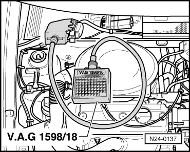
These signals from the air conditioner cause the initial control value for the idling stabilization to be increased when the air conditioner compressor switches in. Thereby the idling stabilization remains in the middle of the regulating range.

Special tools, testers and auxiliary items

  • ◆ Fault reader V.A.G 1551 or vehicle system tester V.A.G 1552 with cable V.A.G 1551/3
  • ◆ Test box V.A.G 1598/18
  • ◆ Hand multimeter V.A.G 1526 or multimeter V.A.G 1715
  • ◆ Adapter set V.A.G 1594
  • ◆ Current flow diagram

Test conditions

  • ● Function of air conditioner OK.
  • ● Air conditioner switched off
  • ● No faults stored in fault memory
    , interrogating fault memory
  • ● Interior of vehicle has room temperature (above 15 ° C)

Test sequence

  • ‒ Connect fault reader V.A.G 1551 (V.A.G 1552) and select engine electronics control unit (address word 01); carry out selection at idling.
    => Page 01-3
 
→ Indicated on display:
Rapid data transfer     HELP
Select function XX
  • ‒ Input 08 for "Read measured value block" function and confirm with Q.
 
→ Indicated on display:
Read measured value block     HELP
Input display group number XX
  • ‒ Input 01 for "Display group number" and confirm with Q.
 
→ Indicated on display:
(1...4 = Display zones)
Read measured value block     1     ⇒
     1     2     3     4
  • ‒ Observe display zone 4 -8 digit number block-:
  • 4th and 5th position from right must display 0
         Display: 11000010
  • ‒ Switch on air conditioner (lowest temperature and highest blower speed).
  • 4th and 5th position from right must now display 1
         Display: 11011010
  • 4th position from right = air conditioner switched on
    5th position from right = air conditioner compressor switched on

If the display does not indicate as described:

 
N24-0137
  • ‒ → Connect test box V.A.G 1598/18 to control unit wiring loom.
  • ‒ Check wiring between test box sockets 33 and 35 and the air conditioner for open circuit according to current flow diagram.
         Wire resistance: Max. 1.5 ω

Matching engine electronic control unit to electronic immobilizer > < Checking control unit voltage supply